Introduction
This article is a continuation of part 1, where you can check the first 5 tips. Here you will find the next 5 tips when working with Tekla Structures drawings.
6. Link dimensions and flip outside dimension
When you have a complex shop drawing, it is helpful to link a vertical with a horizontal dimension that measures the same thing. To do that, select the two measurements and click the “link dimensions” command in the ribbon.

For example, these two dimensions measure the same cope of the beam. You can also write a note like “COPE” in the tags tab.


To predetermine which side will short dimensions go to the outside, use the “Flip outside dimension” option. Simply click on the dimension, and it will flip it to the other side.


Also, if you want to position the text in the first place, the order that you pick is crucial. The second point places the dimension to that side.
7. Change drawing color
You can choose the color of the drawing to be:
1. Color
Color mode is helpful in efficiently assigning the thickness of all the lines.

2. Black and white
In Black and white mode, you can preview the printing settings.

3. Grayscale
In grayscale mode, the first seven colors are shown in black, while the other seven colors are shown in different shades of grey.

To do that. go to File -> Settings -> Color mode or press the default shortcut “B” to cycle through the color modes.
8. Column marks in GA drawings
The default setting for column marks on GA drawings is set to 45 degrees. If you want to change that to standard marks go to (file -> settings -> advanced option (Ctrl + E) -> Marking: parts) and change the value of XS_DO_NOT_DRAW_COLUMN_MARKS_AT_45_DEGREES_IN_GA_DRAWING to TRUE. Reopen the drawing for the change to take effect.


9. Add parallel dimension
When you try to dimension sloped elements, one way is to use the ‘Add free dimension’ command to define the direction and then add the points you want to measure.

But a better way is to use the ‘Add parallel dimension’ command. You first define the direction by picking two points, and then you add the desired dimension.

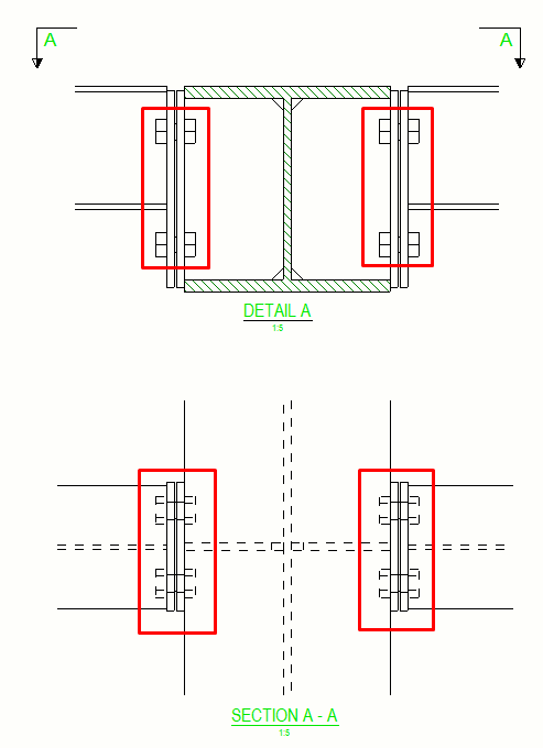
10. Show bolts behind element
Bolts and studs that are behind other objects are not shown in drawing views by default.
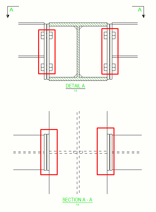
To show them, you need to modify these advanced options. Type ‘bolt’ in the search bar, in all categories. You need to change them to TRUE or AS_PART. Be aware that they will not show in the existing views. The modification will apply to the created views after changing the advanced options. So you need to re-create the view to make the bolt hidden lines visible.

*Bonus tip – alt keys for the most used symbols:
- alt + 0216 = Ø
- alt + 0176 = °
- alt + 0177 = ±
If you read something you liked on our website, or we helped you with an issue, consider buying us a coffee!