Either you are new to Tekla Structures, or already use it for a couple of years, there are always new things you can learn. We should always strive to increase our productivity.
1. Tekla Base Points
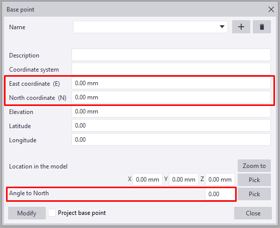
You can adjust the datum level of the model by changing the value of elevation in the base point menu. This is helpful when you want to show the model’s elevation in the real world. By default, the datum level is set to 0, which means that the 0 level in the model has no offset.
In order to define base points, go to File – Project properties – Base points.
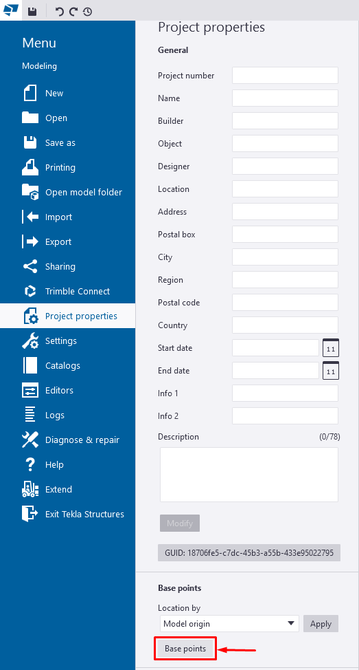
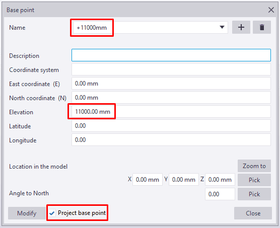
For example, suppose you are modeling a canopy on a rooftop. In that case, It is much better to lower your model closer to 0 and use the base point to adjust the elevations on the drawings rather than to put your model thousands of millimeters above 0. Input the elevation value in the field and thick the box – Project base point.
Also, when you import IFC in Tekla Structures, always set the base points so the model is imported near the origin. It is recommended that your model in Tekla is positioned as close as possible to the model origin because Tekla loses accuracy when snapping, modelling and creating drawings if you are far away from the origin.
It is good practice to ask for the reference point of the IFC model, as well as the North and East coordinate and the angle to True North, from the architect/manufacturer you are receiving the IFC. Then input those values in the Tekla base points fields, so the imported model is in origin.
2. Referencing to Architectural or MEP PDF Drawings
Inserting a pdf is relatively straightforward but before you import one you need to ensure some things:
- The PDF drawing needs to be a vector pdf (created with vector based software like a cad system)
- Raster or scanned images will not work when inserted in Tekla
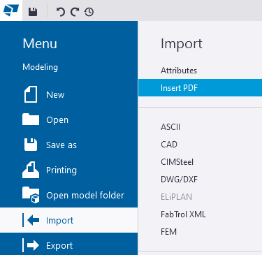
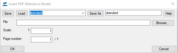
To insert a pdf drawing, go to File – Import – Insert PDF.
Next, input the correct page number you want to be inserted from the pdf file, choose the scale, and then pick the insertion point.
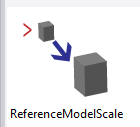
If you don’t know the exact drawing scale, you can use the ReferenceModelScale component from the applications & components side pane. Double-click on the icon and select the pdf. Choose two points with a known distance, then provide the actual distance between the points you pick, and the reference model is scaled.
You can use the pdf reference drawings to check the model for mistakes or use it as a layout to build the model on top of it directly. You can also use the pdf reference drawing to include it in the Tekla Structures drawings to show some terrain details, copings, etc.
Remember to change the work plane to vertical if you want to insert an elevated view reference drawing.
Download our e-book with 20 Tekla Structures Tips & Tricks 👇

3. Clone Drawings
When there are similar parts or assemblies with different position numbers, consider using clone drawings option. You have to first create and modify one drawing for an assembly and then use it as a template for the others. It is really helpful for trusses, railings etc.
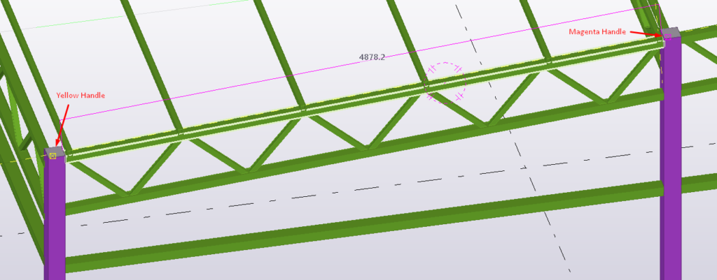
It is important to check that the main parts of the similar assemblies have the same orientation. Inquire assembly objects option highlights the main part of the assembly.
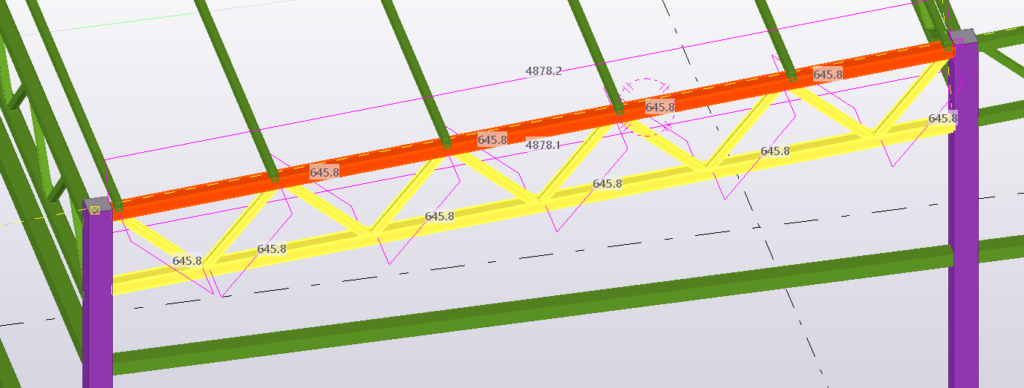
You can check the orientation by looking at the main part color handles. The handle of the starting point is yellow, and the endpoint is magenta. If they are not the same, you can use swap handles macro to change the direction of the profile.
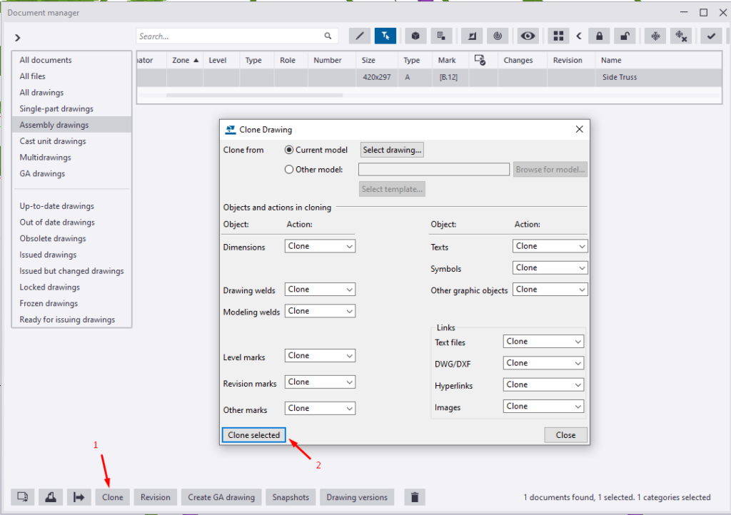
To use the clone drawing option:
- Select the assembly you wish to create the drawing for
- Select the drawing that will be used as an example/template
- Click Clone in the document manager window
- Choose the cloning parameters and click clone selected
4. Color Representation
Use this option to assign the color and transparency of model objects in all model views. Also, you can create customized presentations to show certain objects with the same color or find and eliminate model mistakes. There are various ideas where you can use different object representation templates. I will give you a few examples to get the idea.
- Show model phases
- Show installed elements
- Bolt sizes
- Bolt workshop/site
- Material grades
- Steel plate thickness
- Show locked objects
- Show unnumbered elements
- Element weight, length, or height.
If your model is split into phases and you choose ‘Color by phases’, it will show all your phases with different colors.
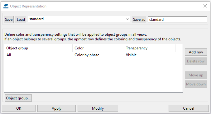
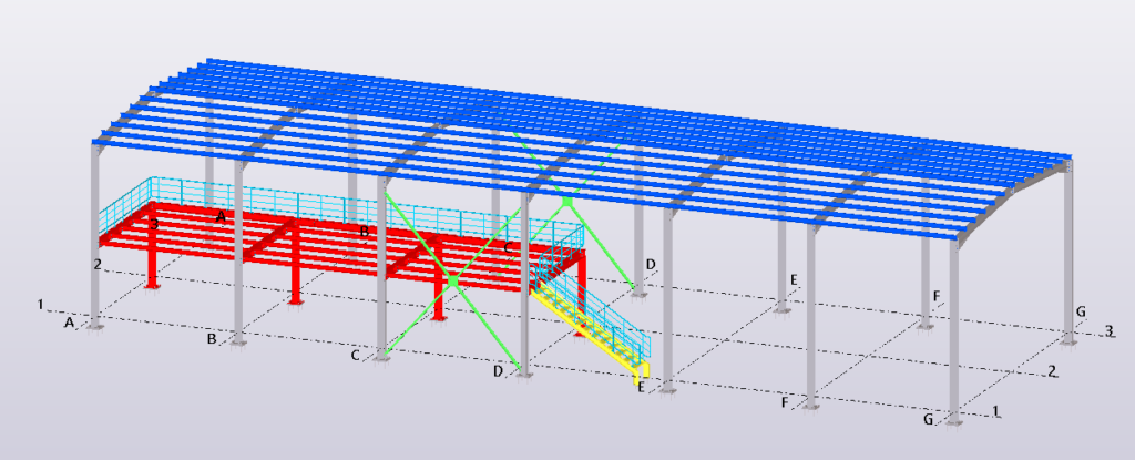
Below is an example where all different phases are shown with different colors”
- Frames = grey
- Platform = red
- Bracing = green
- Purlins = blue
- Railings = cyan
- Stairs = yellow
5. Creating Model Template
Model templates help you save standard properties and settings, so any new project you create is ready to use. You can create multiple model templates, for example, for multiple customers because they all have their own requirements. You can save the model templates locally or on a server so every one of your team can use them.
Model templates are handy for saving settings like item shapes, advanced options, custom components or project properties, so you don’t have to import them repeatedly for every new project. All other things, like saved drawing properties, profile settings, dimensioning styles etc., can be saved in the firm folder.
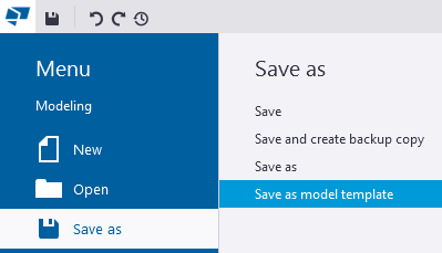
Once you have set your model template with all the things you want to be part of your model template, go to File – Save as – Save as model template. Name your template depending on the purpose, for example customer name.
Now for every new project that you start, you will have the option to choose this sample template model and there will be anything in there that you have set up.
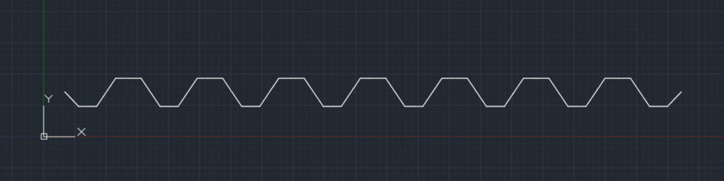
6. Create New Profile From DWG/DXF File
Sometimes you need to create your own custom profile, for example, custom deck shapes, claddings or gutters. A lot of stuff can be created through the profile catalog, but maybe you already have the DWG section to work with and just want to import it to Tekla Structures.
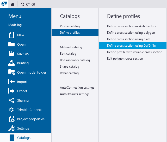
To define a DWG section, go to File – Catalogs – Define profiles – Define cross section using DWG file and choose the file you want to use as a template. Then define the section and profile name. You can also change the profile attributes. Once you click apply, you have created the profile.
Some things to watch out for before you make the DWG file ready to use:
- Delete any kind of dimensions
- Delete all extra lines, and leave only the shape in the file
- Make sure the shape is a close polygon
- Check for gaps or overlapping lines
Also keep in mind that Tekla works in metric, so if you do imperial to metric conversion you have to scale the shape by 25.4.
7. Create New Material
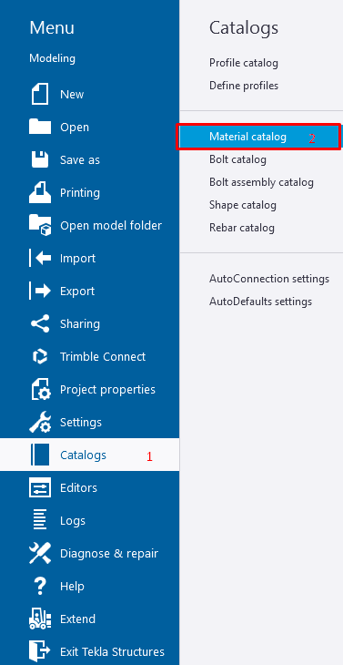
Sometimes there is a need to create new material in Tekla Structures. To do so, open the material catalog – File – Catalogs – Material Catalog.
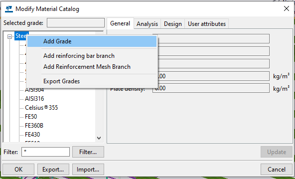
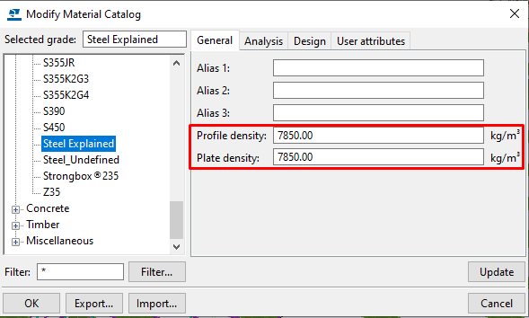
Right click on steel and choose add grade. Rename the grade as you wish and fill in the required fields.
If you are not using the analysis and design options in Tekla Structures, adding profile and plate density is enough because they are necessary to calculate the weight of the elements.
8. Set Thumbnail Screenshot
A Thumbnail photo helps you better visualize the project when opening one in Tekla Structures. It is pretty simple to add one. Just open the project and set the view as you want to be in the thumbnail screenshot. Redraw the view while holding Shift + Ctrl to remove the work area lines for a cleaner photo.
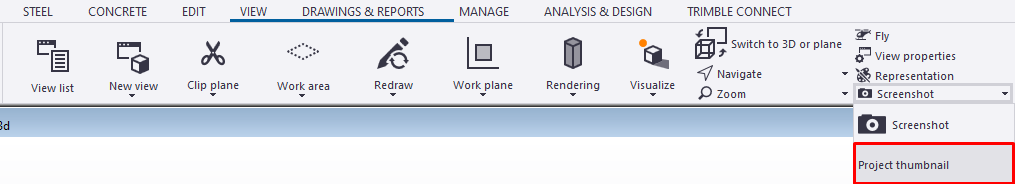
Then on the view tab, click screenshot – project thumbnail and choose the view you have already prepared. And that’s it. You have created your project thumbnail screenshot.
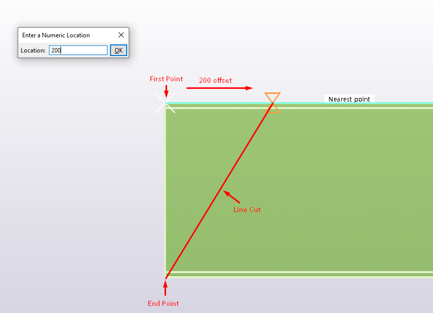
9. Holding CTRL For First Point
Holding CTRL while moving/cutting in Tekla Structures offsets the first point. For example, when creating an angle cut on a profile, hold ctrl at the first point, enter a numeric number for the horizontal distance and finish the cut in the opposite corner.
10. Show With Exact Lines
Show with Exact Lines command is useful when you want to check for clashes between elements or bolts with elements.
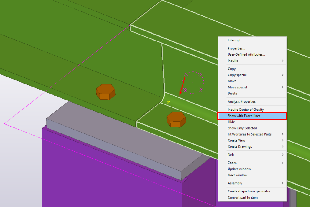
For example, when you want to check the distance between the bolts and the profile radius. (see photo).
*Bonus Tip: Construction Lines Magnet Option
There is an option in Tekla Structures for a magnetic grid plane. That means that when you move the grid, all the handles that are binded to the grid will move with it.
You can also use the magnetism on construction lines and planes.
Learn more about this tip in this video.
If you read something you liked on our website, or we helped you with an issue, consider buying us a coffee!