Introduction
In this article, I will present some useful tips when working with Tekla Structures drawings. Some are less and some more commonly used, but it is still good to know them all.
1. Revision cloud size
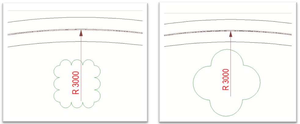
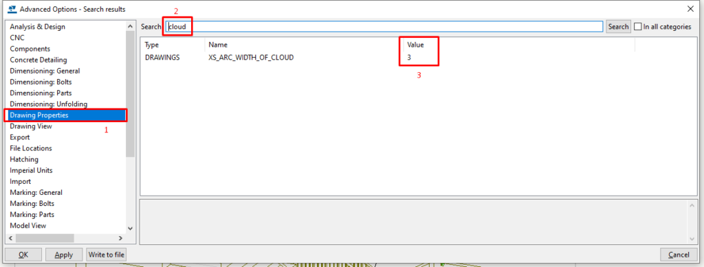
When issuing a revision pack of drawings, you usually need to mark the modified parts and dimensions in the drawing. You can do that with “draw cloud” option. In some cases, the cloud scale does not coincide with the drawing scale, and it looks messy. To make the drawing cleaner, you can change the arc width of the cloud. Go to file -> settings -> advanced option (Ctrl + E) -> Drawing properties and in the search bar type “cloud”. Try changing the value to suit your drawing, “3” works fine most of the time.
2. Dimensioning curved members
Sometimes when you try to dimension radiused or curved sections, you come up with incorrect dimension strings. I want to show you how to get them in there correctly.
If you try to measure the radius and pick three random points from the member centerline, you will often come with an incorrect dimension. To get an accurate radius dimension, you need to select the segments that the member is made of. The curved member is automatically segmented by Tekla, even if you can’t see it. You can adjust how smooth the curve is visually, but it is still composed of segments. You need to use snap override and choose “end”, and then you search for the segment end. Repeat that for all three points required to measure the radius.
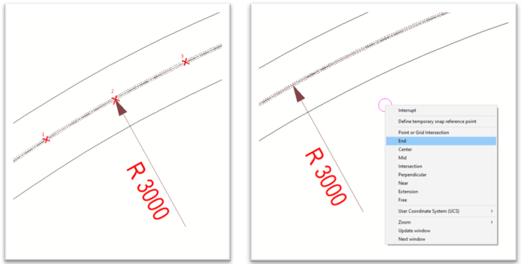
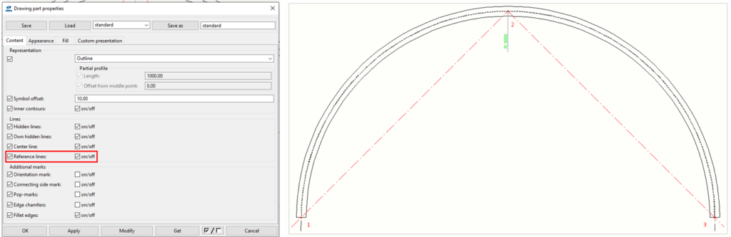
Another way is to turn on the reference line of the part I click on those three points.
3. Dual dimensions
If you ever need to show both metric and imperial dimensions on the same drawing, there is a way in Tekla. To set this up, go to file -> settings -> options and then select “Drawing dimensions”. Under dimensions in tags, set up the secondary dimensions you want to use. If you use the metric system as primary, here, choose imperial. Also, check the boxes for drawing types you want to apply the dimension to automatically.
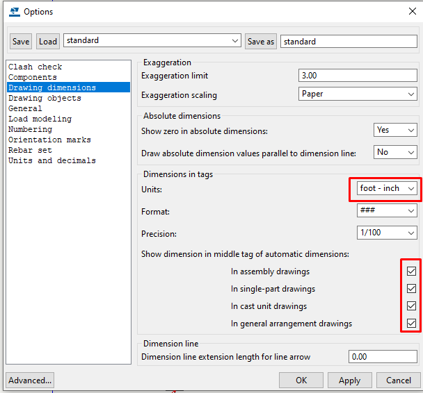
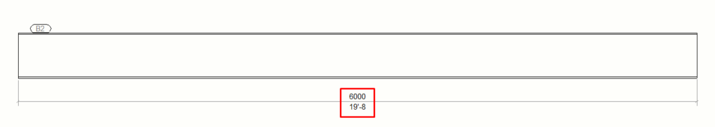
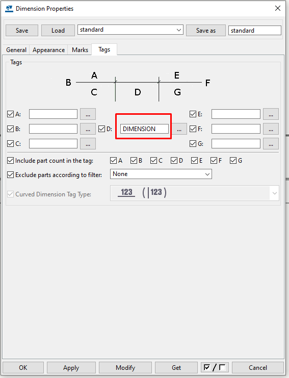
Suppose you want to manually set this for just some dimension on the drawing, open dimension properties, and type “DIMENSION” under tags. It will show both metric and imperial string just for that dimension.
4. Superscript
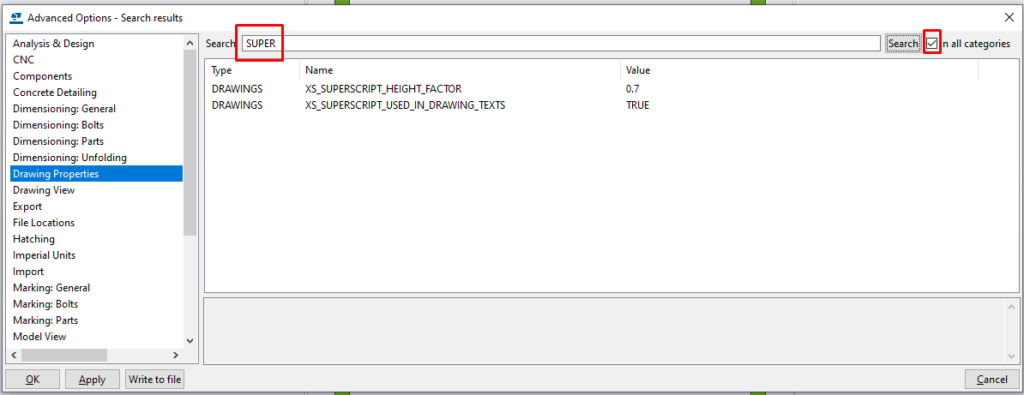
Here is a way to add a superscript in the drawing text. Superscript is a text or symbol written above the standard line of the text and is smaller than the regular text. To get started, go to advanced options and search for “Super” in all categories.
Both rules are pretty straightforward.
Set SX_SUPERSCRIPT_USED_IN_DRAWING_TEXTS to TRUE if you want to use superscript or else set it to FALSE.
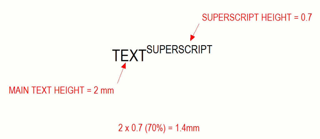
XS_SUPERSCRIPT_GEIGHT_FACTOR is a percentage of the text height that you are adding the superscript to.
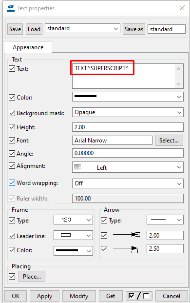
To add a superscript in Tekla drawing, put the superscript text between two “caret” (shift + 6) symbols in the text box dialog. Superscript can also be an entire sentence or even a symbol.
5. Datum level
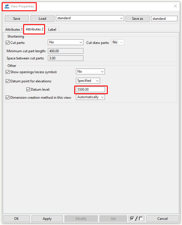
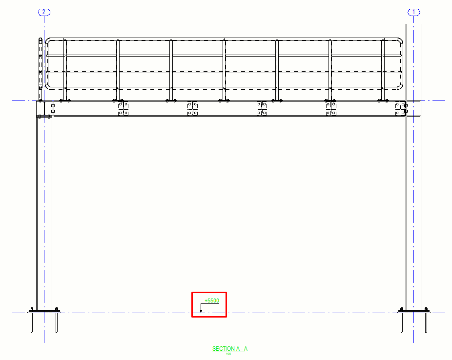
You can adjust the level mark command by changing the value of the datum level in the view settings of the drawing. This is helpful when you want to show the model’s elevation in the real world. By default, the datum level is set to 0, which means that the 0 level in the model has no offset.
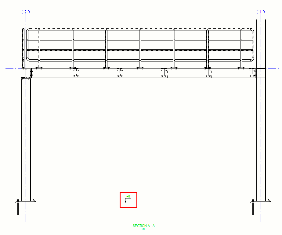
But let’s say that the real elevation of the bottom of the columns is +5500mm. To display that, you simply need to input that value as datum level in the Attributes 2 tab with a minus sign In front of it. The level mark command will now take that value as a reference for all elevations in the drawing. It is much better to lower your model closer to 0 and use the datum level to adjust the elevations on the drawing rather than to put your model thousands of millimeters above 0.
Check the next 5 tips in part 2.
If you read something you liked on our website, or we helped you with an issue, consider buying us a coffee!