The load of the steel columns is transferred to the ground through the concrete foundations. As the stresses in steel are much higher than those in concrete, the forces from the column, which are concentrated in the thin walls, must be distributed at the foot of the column over a larger area so that the pressure in the concrete foundation is within the allowed limits. Therefore the steel column needs a foot in the form of a steel plate.
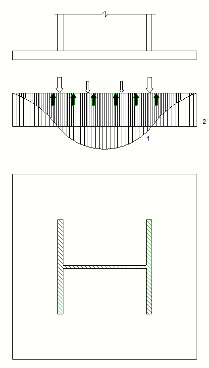
1. The stress in the concrete below the base plate is lower at the edge and increases to its maximum below the column (1). For static calculation, the stresses in the concrete under the base plate are generally calculated with an even distribution (2).

2. Due to the column forces, bending stress occurs in the base plate. To receive these stresses, the base plate must be dimensioned with sufficient thickness or must have stiffening ribs.

3. In addition to the vertical load, the fixed column is also exposed to the bending moment.
Diagram 1 – The bending moment is small in relation to the vertical force.
Diagram 2 – At higher bending moments, tensile forces occur at the edge of the base plate, which must be accepted by appropriate anchors.
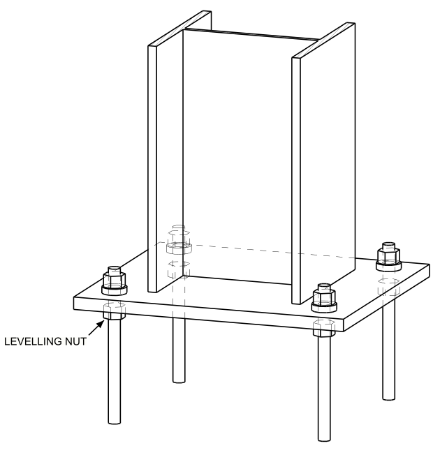
4. Due to different construction tolerances, the upper surface of the foundation is held around 30 mm deeper than the lower surface of the base plate. During installation, the column is placed on levelling nuts, which allows subsequent adjustment of the column.
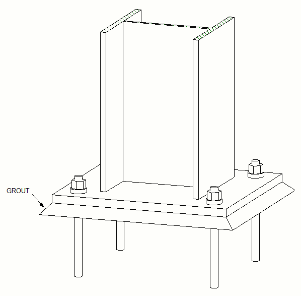
5. After the adjustment is completed, the gap under the base plate is filled with special high-quality concrete/grout.

6. The thick base plate under the pillar requires more material but less workshop time compared to Figure 8. Also, this type of base plate has a lower construction height.
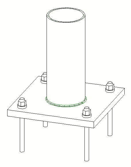
7. The pipes are also placed on a base plate without ribs. For thin plates, radially positioned ribs are required.
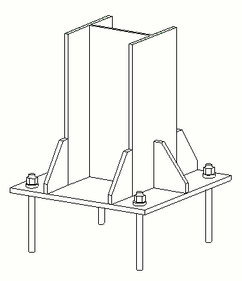
8. Making a base plate for a column of H profiles with a thin plate and ribs. The ribs are placed on the flanges and on the profile web. This construction of the base plate weighs less than the previous one in Figure 6, but it has a higher construction height and is more expensive. The facade elements should also be positioned higher from the ground level so there is no collision with the ribs.

9. A box-shaped column with a thin base plate. The ribs transfer the forces to the walls of the profile section.
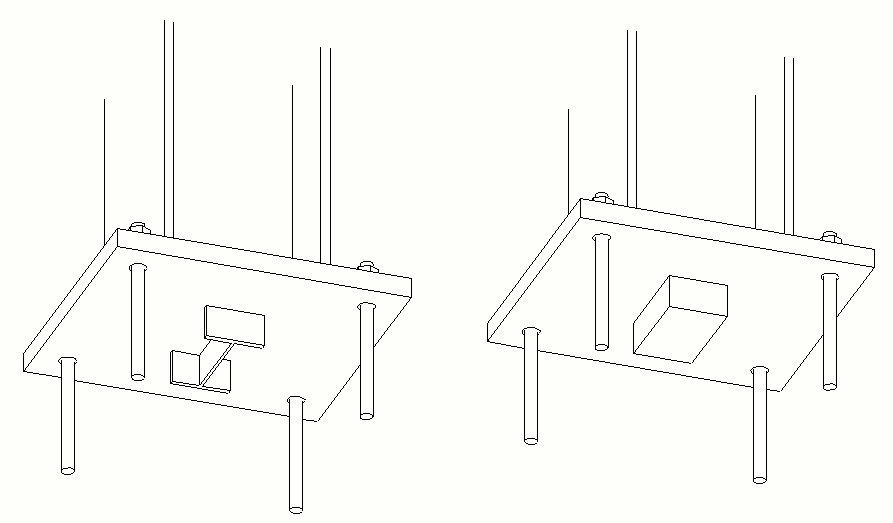
10. For the transfer of horizontal forces to the foundations (shear force transfer), the anchor rods and the frictional force due to the load on the column is often sufficient. At higher horizontal forces and lower loads or negative supporting forces (for example, due to wind), additional parts should be welded under the base plate for stud effect, which are inserted into the appropriate openings. For example, welded steel blocks or welded profile parts.