Vibrations in steel-framed structures, particularly those caused by human activities, are a critical serviceability concern in structural design. Ensuring that vibrations remain within acceptable limits is vital for both occupant comfort and the protection of sensitive equipment.
As Nikola Tesla famously said:
If you want to find the secrets of the universe, think in terms of energy, frequency and vibration.
– Nikola Tesla
This quote is particularly relevant when designing steel-framed structures, where managing vibrations is crucial to ensure safety and comfort. This article provides insights into the causes, evaluation, and mitigation of vibrations in steel-framed structures.
Why Vibration is a Serviceability Issue
Humans are highly sensitive to vibrations, perceiving even the slightest movements. Structural vibrations in environments like offices and residences can cause discomfort and annoyance at really small displacements. Similarly, sensitive equipment such as MRI scanners and electron microscopes can be adversely affected by vibrations, potentially compromising their operation.
Types of Steel-Framed Systems and Vibration Concerns
Various steel-framed systems, including floors, balconies, monumental stairs, and pedestrian bridges, need to be evaluated for vibration serviceability. Long-span systems and lightweight structures are particularly susceptible. It’s crucial to consider vibration effects during the design stage to prevent issues in completed structures.
Resonance and Its Impacts
Resonance occurs when the forcing frequency of human activities matches a structure’s natural frequency, leading to significant vibrations. For instance, walking at 2 Hz on a floor with a 4 Hz natural frequency can cause severe vibrations due to the second harmonic. Designing to avoid resonance frequencies can mitigate such issues.
An interesting real-world example of the impact of resonance is the military practice of prohibiting soldiers from marching in unison while crossing a bridge. This rule exists because the synchronized footsteps can match the bridge’s natural frequency, potentially causing dangerous resonant vibrations. Historical incidents have demonstrated that such resonance can lead to structural failures, emphasizing the importance of accounting for resonant effects in structural design.
Broughton Suspension Bridge, England (1831):
One of the earliest recorded incidents of resonance-induced failure occurred when British soldiers marched in unison across the Broughton Suspension Bridge in Manchester. The synchronized marching caused the bridge to vibrate violently, leading to its collapse. This incident prompted the British Army to adopt the rule prohibiting soldiers from marching in step across bridges.
Tacoma Narrows Bridge, USA (1940):
Although not caused by marching, the collapse of the Tacoma Narrows Bridge, also known as “Galloping Gertie,” is a classic example of resonance leading to structural failure. Wind-induced vibrations matched the bridge’s natural frequency, causing dramatic oscillations that ultimately led to its collapse. This incident highlighted the need for considering aerodynamic effects and resonance in bridge design.
Causes of Annoying Vibrations
Annoying vibrations primarily result from the matching of activity frequencies (walking, running, exercising) or their harmonics with a structural system’s natural frequency. Common sources of complaints include vibrations during concerts or sports events on balconies or stadiums.
Here are some well-known real-life examples:
Hokie Wave at Lane Stadium, USA:
During football games at Virginia Tech’s Lane Stadium, fans perform the “Hokie Wave,” where synchronized jumping and cheering can create noticeable vibrations in the structure. While this has not led to any structural failures, it highlights how collective human activity can induce significant vibrations.
London Millennium Footbridge, England:
On the day of its opening in 2000, the London Millennium Footbridge experienced unexpected swaying due to the synchronized footsteps of pedestrians along with a strong wind. This phenomenon, known as synchronous lateral excitation, caused the bridge to vibrate significantly. Engineers had to retrofit the bridge with dampers to mitigate the vibrations and ensure safety.
Myths and Realities About Floor Vibrations
Several misconceptions exist regarding floor vibrations, such as the belief that open-web steel joists inherently cause vibration problems or that cambering improves vibration response. In reality, compliance with design guides ensures acceptable vibration performance, and factors like composite action and damping play more significant roles in vibration behavior than previously assumed.
Evaluation Criteria for Vibration Serviceability
Evaluating the vibration performance of a structure involves understanding various parameters:
Natural Frequency
The fundamental natural frequency of a structure is determined by its mass and stiffness. It can be calculated using classical vibration theory or finite element analysis. Floors with natural frequencies below approximately 9 Hz are more likely to experience resonant responses to walking.
Here’s a step-by-step guide to calculating the natural frequency of a simple steel beam:
1. Determine the Properties of the Beam:
- Material Properties:
Modulus of Elasticity (E): For steel, E≈29,000 ksi (or 200 GPa).
- Geometric Properties:
Length (L): The span of the beam.
Moment of Inertia (I): This depends on the beam’s cross-sectional shape.
Mass per unit length (m): This is typically the weight per unit length divided by the acceleration due to gravity (g).
2. Basic Equation for Natural Frequency:
For a simply supported beam, the fundamental natural frequency (𝑓) can be approximated using the following formula:
![\[f = \frac{1}{2π} \sqrt\frac{k}{m}\]](https://steelexplained.com/wp-content/ql-cache/quicklatex.com-65ab6f35237a05d04c58f18ad9213cd3_l3.png "Rendered by QuickLaTeX.com")
where:
- k is the stiffness of the beam.
- m is the mass per unit length of the beam.
3. Calculate the Stiffness (k):
For a simply supported beam, the stiffness can be calculated using:
![\[k = \frac{48EI}{L^3}\]](https://steelexplained.com/wp-content/ql-cache/quicklatex.com-6cd81b45929dffc57149388258952563_l3.png "Rendered by QuickLaTeX.com")
where:
- 𝐸 is the modulus of elasticity.
- 𝐼 is the moment of inertia.
- 𝐿 is the length of the beam.
4. Calculate the Mass per Unit Length (m):
![\[m = \frac{w}{g}\]](https://steelexplained.com/wp-content/ql-cache/quicklatex.com-2319b7402994f4684166aac920698dc9_l3.png "Rendered by QuickLaTeX.com")
where:
- w is the weight per unit length of the beam.
- g is the acceleration due to gravity (9.81 m/s2 or 386 in/s²).
5. Substitute into the Frequency Formula:
Substitute k and m into the natural frequency equation:
![\[f = \frac{1}{2π} \sqrt\frac{48EI}{L^3 m}\]](https://steelexplained.com/wp-content/ql-cache/quicklatex.com-ceb20b99fe11e9e9c242c0559643b70e_l3.png "Rendered by QuickLaTeX.com")
Example Calculation:
Assume a simply supported steel beam with the following properties:
- Length (L) = 10 m
- Modulus of Elasticity (E) = 200 GPa
- Moment of Inertia (I) = 8 × 10⁻⁶ m4
- Weight per unit length (w) = 300 N/m
Steps:
1. Calculate the mass per unit length (m):
![\[m = \; \frac{w}{g} = \frac{300}{9.81} \approx 30.58 \; kg/m\]](https://steelexplained.com/wp-content/ql-cache/quicklatex.com-de7c3b6cf02b421cee9727ee69457075_l3.png "Rendered by QuickLaTeX.com")
2. Calculate the stiffness (k):
![\[k = \frac{48 * 200 * 10^9 * 8 * 10^{-6}}{10^3} = 768 \; MN/m\]](https://steelexplained.com/wp-content/ql-cache/quicklatex.com-430b13093bb29245c244f4d8681e29a6_l3.png "Rendered by QuickLaTeX.com")
3. Substitute into the frequency formula:
![\[f = \frac{1}{2π} \sqrt\frac{768 * 10^6}{30.58} \approx \frac{1}{2π} \sqrt {25.11 * 10^6} \approx 25.24 \; Hz \]](https://steelexplained.com/wp-content/ql-cache/quicklatex.com-37144bd3abcee29bae4d20df1c1f4a84_l3.png "Rendered by QuickLaTeX.com")
Thus, the natural frequency of the simply supported steel beam is approximately 25.24 Hz.
Note: This is a simplified approach and real-world calculations may involve additional factors such as boundary conditions, higher modes of vibration, and damping effects. For complex structures, numerical methods like Finite Element Analysis (FEA) are often used to obtain more accurate results.
What Does 25.24 Hz Mean?
The frequency at which a system tends to oscillate in the absence of any driving or damping force. For the steel beam, 25.24 Hz means that if the beam is displaced from its equilibrium position and then released, it will naturally oscillate at this frequency.
Hertz (Hz) is the unit of frequency, representing cycles per second. Thus, 25.24 Hz means the beam would complete 25.24 cycles of oscillation per second.
If the natural frequency of 25.24 Hz coincides with the frequency of applied dynamic loads (such as machinery vibrations or rhythmic activities like dancing), resonance can occur. To avoid resonance, engineers ensure that the operational frequencies of applied loads do not match the natural frequency of the structure. For example, if a machine operating at 25 Hz is installed on the beam, measures like adding dampers or changing the beam’s stiffness or mass might be needed.
Design Validation: Engineers compare the natural frequency to standard values to ensure the design meets vibration criteria. For typical floor structures, frequencies below 9 Hz might indicate susceptibility to human-induced vibrations, while frequencies above 9 Hz generally suggest lower risk.
Damping
Damping refers to the dissipation of vibratory energy over time. It is expressed as a percentage of critical damping and varies based on the presence of nonstructural elements like ceilings and partitions. Higher damping ratios generally result in lower resonant responses.
Forcing Frequency and Mode Shapes
The forcing frequency is the rate of impacts from human activities, and mode shapes represent the spatial patterns of vibrations at natural frequencies. Understanding these aspects helps in predicting and mitigating vibrations.
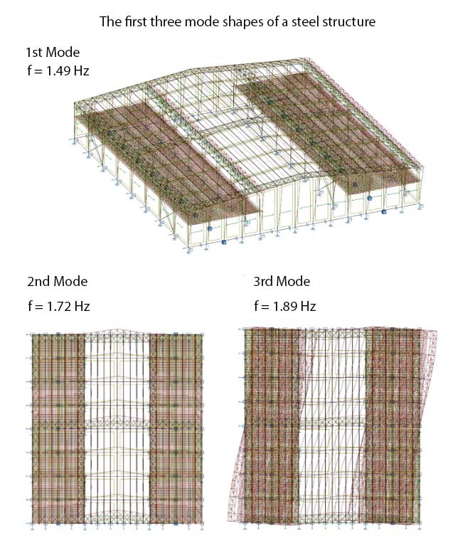
Modal analysis is specifically used in the calculations of natural frequency, damping, and mode shapes. It plays a critical role in understanding the dynamic behavior of a structure. Here’s how modal analysis fits into the above calculations:
Modal Analysis Usage in natural frequency calculation:
- Finite Element Analysis (FEA): Modal analysis via FEA helps determine the natural frequencies of complex structures more accurately. While the simple beam example uses classical vibration theory, for real-world structures like entire buildings, bridges, or irregular geometries, FEA is indispensable.
- Process: During FEA, the structure is modeled, meshed, and subjected to modal analysis. The software solves the eigenvalue problem to determine the natural frequencies and corresponding mode shapes.
Example: In the example of calculating the natural frequency of a steel beam, if the structure were more complex (e.g., a steel frame with multiple beams and columns), modal analysis using FEA would be conducted. The output would provide the natural frequencies of the entire structure and its components.
Modal Analysis Usage in damping calculation:
- Determining Mode Shapes and Damping Ratios: Modal analysis identifies mode shapes, which help determine how different parts of the structure move relative to each other. This information is crucial when estimating damping.
- Experimental Modal Analysis: Sometimes, modal testing (a form of experimental modal analysis) is performed on existing structures to measure actual damping ratios and natural frequencies, which can then be used to validate or adjust the FEA models.
Example: In the damping calculation example, if modal analysis identified that a particular mode shape involved significant movement of a non-structural element (e.g., a partition wall), this would be considered when estimating the damping ratio.
Modal Analysis Usage in forcing frequency and mode shapes :
- Mode Shapes: Modal analysis directly provides the mode shapes of the structure, which describe how the structure deforms at each natural frequency. Understanding mode shapes is critical for assessing how the structure will respond to dynamic loads.
- Harmonic Analysis: Using the mode shapes from modal analysis, harmonic analysis can be performed to understand how forcing frequencies (like walking frequencies) interact with the structure’s natural frequencies.
Example: In the example calculating forcing frequencies and their harmonics, modal analysis would provide the mode shapes. These shapes are used to assess how forces at different frequencies will affect the structure. For instance, if the first mode shape shows maximum displacement at the floor’s center, this area is critical for assessing vibrational impacts from walking or other activities.
By integrating modal analysis into these calculations, engineers can achieve a comprehensive understanding of the dynamic behavior of steel structures, ensuring they are designed to effectively manage and mitigate vibrations.
Practical Considerations for Architects
Architects must account for vibration impacts in their designs to ensure comfort and safety, especially in areas like open-office layouts and spaces supporting rhythmic activities.
Here is how to reduce vibration in steel structure:
- Avoid Long Walking Paths Perpendicular to Beam Spans:
- Design walking paths parallel to beam spans to reduce vibration transmission.
- Use Deeper Structural Members for Longer Spans:
- Select deeper beams and girders to increase stiffness and reduce deflections and vibrations.
- Place Sensitive Equipment Near Girders or Columns:
- Position sensitive equipment, such as medical devices and precision instruments, close to support points to minimize exposure to vibrations.
- Incorporate Vibration Damping Materials:
- Use materials and construction techniques that enhance damping, such as composite floors or damping layers, to absorb and dissipate vibrational energy.
- Design for Higher Natural Frequencies:
- Ensure that the natural frequencies of structural components are higher than common excitation frequencies, typically above 9 Hz, to avoid resonance with walking or rhythmic activities.
- Implement Vibration Isolation Techniques:
- Use isolation pads or mounts under machinery and equipment to prevent transmission of vibrations to the structure.
- Conduct Detailed Modal Analysis:
- Perform modal analysis during the design phase to identify potential resonance issues and adjust designs accordingly.
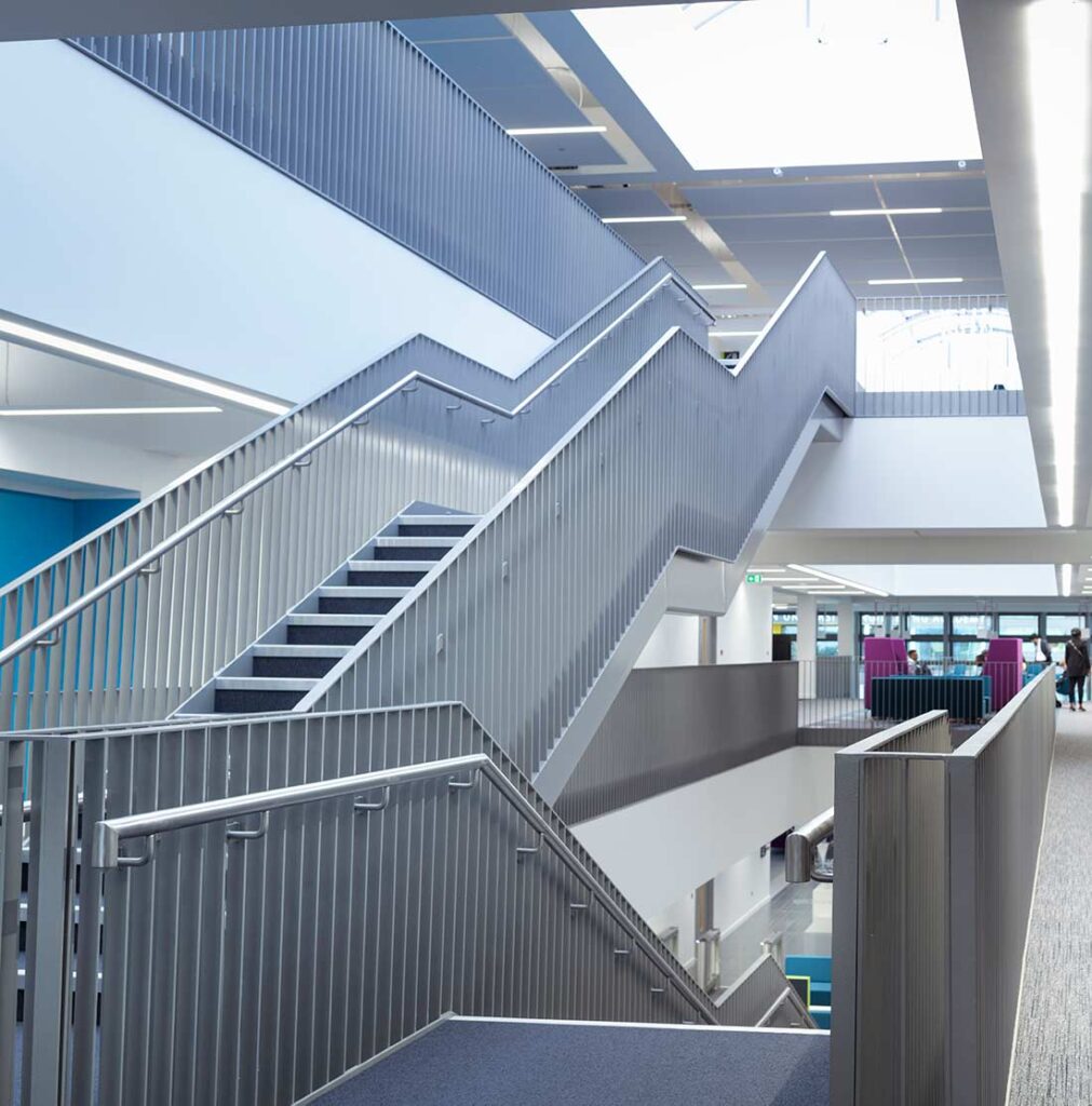
Monumental Stairs and Pedestrian Bridges
Monumental stairs and pedestrian bridges are particularly vulnerable to human-induced vibrations. Design considerations include calculating modal properties, estimating damping, and understanding the unique dynamic loads associated with these structures.
Monumental stairs prioritize aesthetics with long spans and shallow stringers, resulting in low natural frequencies. Due to short stride lengths, step frequencies can reach 2.5 Hz (150 bpm) for regular descents and 4.0 Hz (240 bpm) for fast descents, potentially matching one of the first four harmonics of the dynamic force and causing resonance. These stairs are typically lightly damped and have low mass, making them highly responsive to resonant vibrations.
Measurements and Retrofit Techniques
Measuring the response of occupied floors and retrofitting structures to reduce vibrations are critical steps in maintaining serviceability. Techniques like adding tuned mass dampers or increasing structural stiffness can effectively control vibrations.
Conclusion
Understanding and controlling vibrations in steel-framed structures are essential for ensuring occupant comfort and protecting sensitive equipment. By following guidelines and incorporating thoughtful design practices, architects and engineers can create structures that meet vibration serviceability requirements and enhance overall building performance.
References
- Murray, T. M., Davis, D. B., & Ungar, E. E. (2018). “Facts for Steel Buildings No. 5: Vibration.” American Institute of Steel Construction. Available at: Facts for Steel Buildings No. 5: Vibration
- Murray, T. M., Allen, D. E., & Ungar, E. E. (1997). “Floor Vibrations Due to Human Activity.” AISC Design Guide 11, 1st Edition.
- Murray, T. M., Allen, D. E., & Ungar, E. E. (2016). “Vibrations of Steel-Framed Structural Systems Due to Human Activity.” AISC Design Guide 11, 2nd Edition.
- Smith, A. L., Hicks, S. J., & Devine, P. J. (2009). “Design of Floors for Vibration: A New Approach.” Steel Construction Institute (SCI) P354.


