The most important part of the steel design process is the steel connections calculation. It is up to them whether the construction is optimal and stable. They should be easy to fabricate but strong enough to withstand all the loads. Most of the disasters that happened throughout history are because of poorly designed connections. In this article, we will point out everything you need to look out for when designing one.
There are two main types of steel connections – welded and bolted connections.
Steel Connection Classification: Pinned, Semi-Rigid, and Moment Connections
Before diving into the specific types of steel connections, it is important to understand how connections are classified by their rotational stiffness and load transfer behaviour. All steel connections fall into one of three categories: pinned (simple), semi-rigid, or moment (rigid). Choosing the right classification has a direct impact on your structural model and overall frame design.
Pinned Connections
A pinned connection, also called a simple or shear connection, is designed to transfer only shear force. It allows free rotation at the joint and does not resist bending moment. In your structural model, pinned connections are represented as a hinge. They are the most common type of connection used in braced steel frames where lateral stability is provided by a separate bracing system.
Typical examples include fin plate connections and flexible end plate connections. They are popular because they are simple to fabricate, quick to erect on site, and place no moment demands on the supporting column or beam.
Moment (Rigid) Connections
A moment connection, also called a rigid or fixed connection, is designed to transfer both shear force and bending moment. The joint is stiff enough to maintain the angle between connected members under load. Moment connections are essential in unbraced frames and portal frames where the frame itself must resist lateral loads through frame action rather than bracing.
Full-depth end plate connections with multiple bolt rows, haunched connections, and welded connections are typical examples. The trade-off is that they are more complex to design, more expensive to fabricate, and place significant moment demands on the supporting element — which must be checked accordingly.
Semi-Rigid Connections
In reality, no connection is perfectly pinned or perfectly rigid. Semi-rigid connections sit between the two extremes — they transfer some moment, but not the full elastic moment of the connected beam. Eurocode 3 (EN 1993-1-8) explicitly allows for semi-rigid connection design using the component method, though this adds complexity to the structural analysis.
Partial-depth end plate connections are a common example of semi-rigid behaviour. Unless you are specifically designing for semi-rigid behaviour, it is generally more practical to classify connections as either pinned or rigid and design them accordingly.
| Connection Type | Load Transfer | Typical Examples | Common Use Case |
| Pinned (Simple) | Shear only | Fin plate, cleat | Braced frames, secondary beams |
| Semi-Rigid | Shear + partial moment | Partial depth end plate | Some beam-column joints |
| Moment (Rigid) | Shear + full moment | Full depth end plate, haunched | Unbraced frames, portals |
Tip: Always check which connection classification your structural analysis assumes. If your model treats a connection as pinned but the actual detail is relatively stiff, you may be underestimating the moments transferred to supporting members.
• Welded Steel Connections
Welded steel connections are easier to understand. They can be created in the workshop or on-site. The process is simple, put together two parts and weld around them, at least in theory. Of course, it takes a lot of work to actually do it. Whenever possible, avoid welding on site because the quality of the weld will be worse, it is much more expensive and will slow down the construction.
In practice, the two most used types of weld connections are Fillet Weld – FW and Full Strength Butt Weld.
• Full Strength Butt Weld – FSBW
The Full Strength Butt Weld, as the name says itself, should be designed to transfer the full strength of the section as long as full penetration is achieved. The weld can be made between un-prepared edges for thinner plates, but most of the time is made between chamfered or bevelled parts. It can be a one-side weld or preferably two side weld as material thickness increases. There are numerous types of butt welds, like square butt welds, U butt welds, J butt welds, etc., but the most common is the V butt weld.
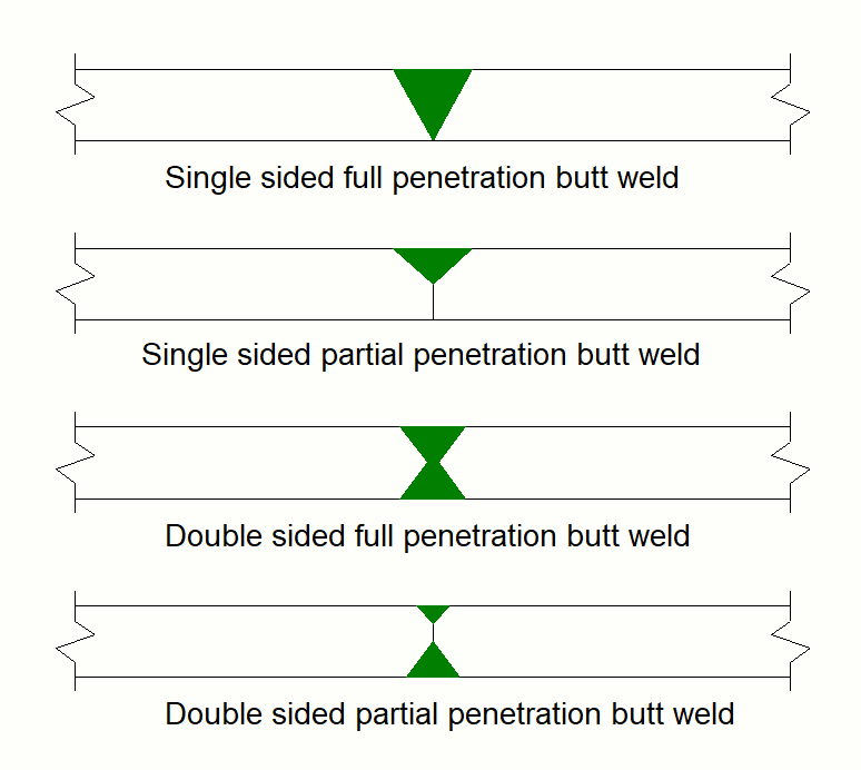
Main elements of a butt weld are:
- Gap – the gap between the workpieces is usually around 2-3mm, and its purpose is to ensure the filler fully penetrates the joint.
- Root – is the edge that has not been bevelled, and is also around 2-3mm thick.
- Groove Angle – is the angle between the prepared faces, and it is around 60°
- Throat – is the shortest distance from the face of the weld to the root.
- Reinforcement – is the metal outside the surface of the workpieces.

Butt welds are most often used when the steel sections are in the same plane.
• Fillet Weld – FW
Fillet Weld is the most used type of welded connection. It is used when joining together two pieces that are perpendicular or at an angle, also known as tee joints or pieces that overlap, known as lap joints. For angles smaller than 60°, the weld should be considered as partial penetration butt weld, and for angles greater than 120° additional resistance testing is required.
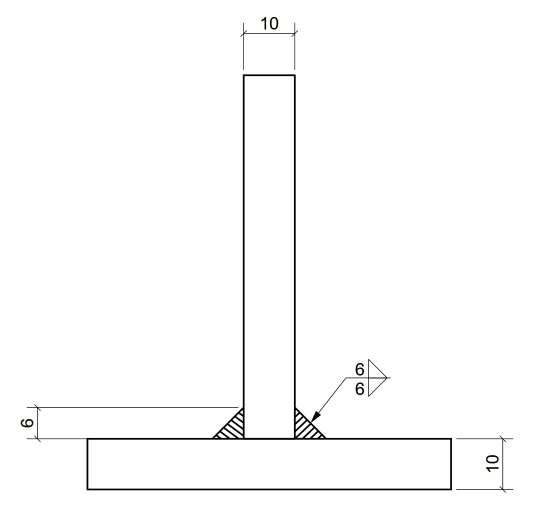
You can have different sizes of fillet welds, starting from 4-5 mm, depending on the load capacity. For example, 6 CFW (continuous fillet weld) achieves around 1 kN/mm, so for 100 kN, you need a 100 mm weld length. Most optimal sizes are up to 6 mm because they can be done with a single-run metal arc process. Bigger welds, more than 8mm, need to be done in multiple paths, leading to more expensive welds.
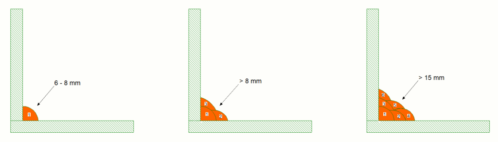
Also, the weld size is limited by the thickness of the base material. If the weld is too big, it can overheat the area and cause local damage. The maximum size of the weld needs to be 3/4 of the thinner plate. For example, if you connect two 10 mm plates, the weld should be at most 7-8 mm. This rule assumes that the weld is from both sides of the plate and it is a full length weld.
If you design the weld for rigidity, in case the stress in the plate is a lot lower than the yield strength, the leg size of the weld can be 1/4 to 3/8 of the thickness of the plate. Intermittent welds are also efficient for a rigidity design.
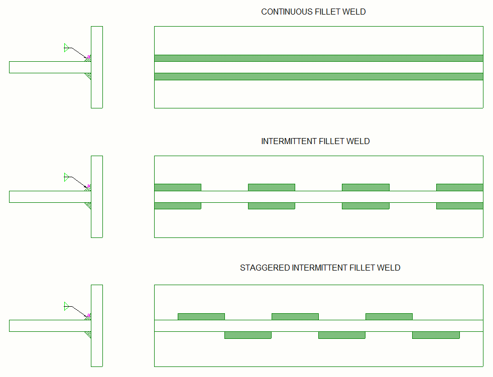
With intermittent welds, you can also avoid steel deformation when connecting long elements. Welding heats up the element, so the steel expands, and the section is welded in its expanded state. Steel tends to return to its normal state when it cools down, but the section will deform if the weld is continuous.
But if you need to weld the sections continuously, you can first add intermittent weld, wait for the steel to cool down and then weld the rest of the area.
• Bolted Steel Connections
The most common method of connecting steel structures is bolting them together. This way, you have better control of the quality of the connection. The holes in the members are drilled precisely in the workshop with modern CNC equipment. The bolts are also manufactured in a factory setting and are subject to tests that prove their load capacity. Bolting is also a cheaper and quicker option.

• Bolt grades and bolt sizes
There are several different grades of bolts you may need to consider when designing a connection. The most common are:
- 4.6
- 8.8
- 10.9
The grade specifies the bolt properties, ultimate tensile strength and yield strength. For example, in bolt grade 4.6: the first number (4) represents the ultimate tensile strength (400 MPa or N/mm2), and 0.6 means that the yield strength is 60% of the ultimate strength of the bolt (240 MPa or 240 N/mm2).

Bolts with grade 4.6 are better for light structures with static loading, members that don’t need high strength. They are least expensive, more versatile, and their advantage is that they can be welded, unlike 8.8 or 10.9, because they are high-strength steel. If you try to weld the 8.8 or 10.9, you won’t achieve the strength you need as the steel becomes brittle.
Why would you weld a bolt?
There are situations when you can’t access the bolt from both sides to tighten it, or you can’t bolt all the way through a section, or maybe as welded studs. For example, when you need to install facade elements.
There are also other options when there is no space for a hand to reach the other side of the bolt. You can weld nuts behind the holes in the section or use tapped holes. If you decide to use tapped holes, make sure the thickness of the element is at least 5mm, so fabricators can actually make the threads inside the drilled hole. Cover this type of hole when the finishes are applied. There are also special kind of bolts for this purpose, but they are much more expensive.

When you need to achieve the exact strength of the steel element, such as bearing beams and columns, then it is better to go with high-strength bolts such as 8.8 or 10.9.
The preferred sizes of bolts used in the construction industry are the following:
- M12
- M16
- M20
- M24
- M30
Bolts are also classified by the tightening procedure:
- Snug tight /S
This expression is a little bit misleading. There are different explanations for this kind of bolts, but generally, they are described as sufficiently tightened bolts to prevent the removal of the nuts without a wrench.
- Bearing tight /TB
TB represents fully tensioned bolts, but under the applied force, the bolts can slip into their usually 2 mm oversized holes.
- Friction tight /TF
TF bolts are only used in joints highly sensitive to movement. Avoid using them wherever possible as they are much more expensive because they require preparing the surface and must be torqued to a higher load.
• Bolts spacing
The spacing of bolts is critical when you design your connections for various reasons.
First, there should always be enough space to allow smooth bolt installation on site. Make sure they are accessible from both sides, and there is room for the installation tool, like a ratchet gun. Second, there should be enough gap between bolts and edges, so there is enough steel in between to transfer the shear force through the connection.
Check the recommended bolt distances below. The values may vary a little in different building codes.
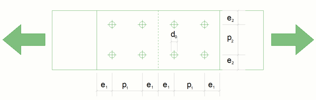
- Pitch distance (p₁) – the distance between bolt centers in the direction of the applied force ~ 2.2d₀ ÷ 2.5d₀
- Gauge distance (p₂) – the distance between bolt centers perpendicular to the applied force ~ 2.4d₀ ÷ 2.5d₀
- End distance (e₁) – the distance between the end of the element to the nearest bolt center in the direction of the applied force ~ 1.2d₀ ÷ 1.5d₀
- Edge distance (e₂) – the distance between the edge of the element to the nearest bolt center perpendicular to the applied force ~ 1.2d₀ ÷ 1.5d₀
- d₀ – hole diameter
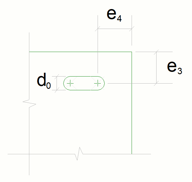
- e₃, e₄ – minimum edge distances ~ 1.5d₀
Bolted steel connections can achieve both pinned or a moment connection.
• Most common types of bolted steel connections
• End Plate Connection
The end plate connection is the most used one. It consists of a welded end plate to the supported beam bolted to the main member, beam or column, on site. To reduce the stiffness of the joint and behave closely to pinned connection, the end plate connection can be designed with partial depth welded to the web only.
The joint resistance is provided by bolts in tension in one flange and compression forces in bearing at the other flange. The vertical shear is assumed to be transferred through the bolts located at the compression flange.
A stiffened end plate connection can be used for open cross sections consisting of welded plate and stiffeners to the supporting member.
Tip: A rule of thumb for an indicative connection is to use a plate thickness equal to the bolt diameter. This way, you will avoid the problem with prying. But, of course, every connection needs to be calculated accordingly.

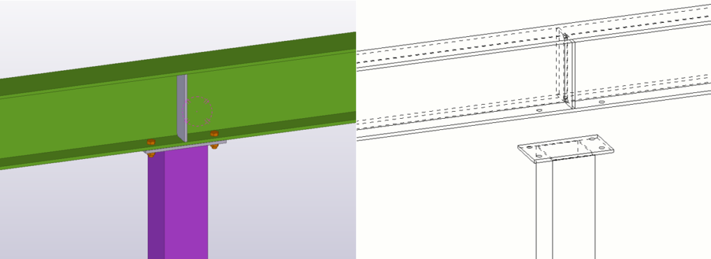
Another variation is the seating end plate connection between a column and a beam. A plate is welded on top of the column and bolted through the beam flanges. Depending on the plate thickness, this connection can be pinned, semi-rigid, or fixed. In rigid connections, stiffeners and haunch plates are also included to limit the flexibility.
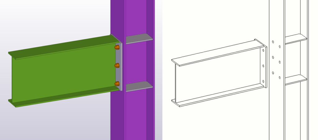
• Fin Plate Connection
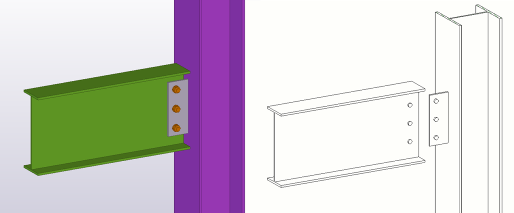
Fin plate connection can be made between beam and beam or between column and beam. It is a simple pinned connection composed of a vertical plate welded to the supporting member, to which the secondary beam is bolted on site. This connection does not transfer moment but only shear force. This connection is popular because it is easy to fabricate and is one of the quickest to erect on site.

The number of bolts depends on the beam depth. A rule of thumb is to divide the depth by 100 to get the number of bolts. For example, a beam with 300mm height will have 3 bolts in a line.
Tip: Because it is not always obvious on site to which side of the fin plate the beam should be bolted, marking the contact side of the fin plate is a good practice.
Be causes when designing one because the center of the bolts is offset from the supporting element center line, so the force creates a moment that the supporting element needs to resist.

• Beam/Column Splice

The splice connection is usually composed of two shear web plates and top and bottom flange plates. In some cases internal flange plates can be included. All these plates have different functions. The web shear plate is where the most of the shear force is transferred. It is actually following the stress diagram of a steel section. The top and bottom flange plates are there to transfer the compression and tension force, they provide the moment fixity. All plates can also be welded on one side and bolted to the other profile.

The need for this type of connection comes from the fact that the size of the assemblies that can be brought on site is limited. The maximum allowed length range is around 12 – 16 meters, depending on the truck’s size.
This connection can be designed as full strength profile capacity or according to the forces applied at that splice. But it should always resist a minimum moment, typically half of the beam capacity. If you make it too weak, you will have problem with too much flexibility and transferring the deflection forces.
Tip: Always place the nut on the bottom because if it ever comes loose and slips, the bolt is still there to provide the shear transfer.

Another way to connect the assemblies is by using the bolted end plate splice. It is most often used for tubular profiles but can also be used for open sections. Because it is a less stiff connection, a good practice is to use thicker plates and put the bolts closed to the flanges to increase the overall stiffness of the joint.
• Bracing Connection
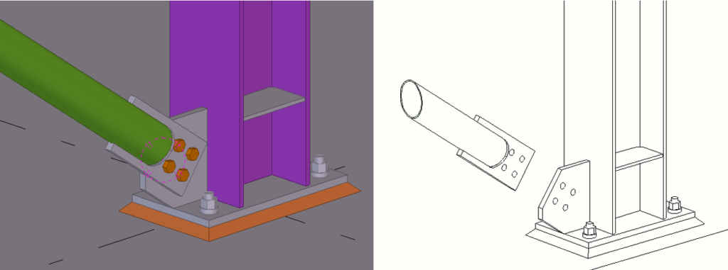
Various steel profiles can be used as bracing members from angles, flats, channels, I sections, hollow sections, etc. They are only loaded with axial load, most of the time, are designed to work in tension only. Bracing members are usually bolted to a gusset plate welded to the supporting element. A rule of thumb for gusset plate thickness is to be at least equal to the thickness of the member connecting to it.
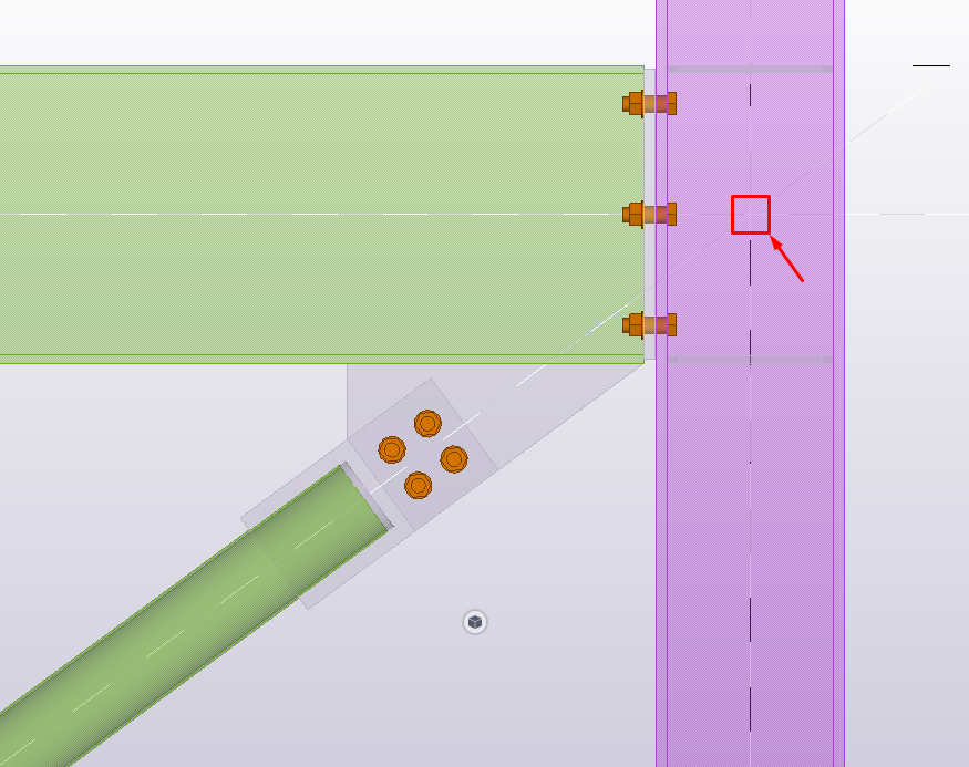
Tip: A good practice is always to try to connect them centrally to the supporting element. Still, sometimes it is more convenient to put them with a bit of eccentricity to create a more compact joint and check locally for the effects of the micro-moment created.
• Base Plate Connection
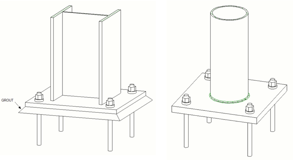
The column base plate is one of the most crucial elements in steel structures. The designer should use caution and good judgment in design and detailing to achieve desired strength, stiffness, and ductility of this important class of connection.
If your base plate doesn’t perform well or fails, you have nothing to hold your structure together, or if you have designed it as pinned but is genuinely more fixed, that will change the whole design process.
The most common reasons for base plate failures are:
- Unexpected early anchor fracture
- Large elongation of the anchor rod
- Plastification of the plate
- Failure of the concrete or the grout under the base plate
- Weld fracture between the column/gusset plate to base plate
Read more about base plate connection principles in our previous article.
Steel Connections in Seismic Design
In seismic regions, steel connections must perform beyond simple strength requirements. During an earthquake, a structure is subjected to rapid, repeated load reversals. Connections must not only carry the design loads — they must also be ductile enough to absorb and dissipate energy without brittle fracture.
The 1994 Northridge earthquake in California was a turning point for seismic connection design. Pre-Northridge moment connections, which used full-penetration welds between beam flanges and column flanges, suffered widespread fractures at relatively low levels of ground shaking. Post-Northridge research led to significant changes in connection design and detailing requirements for seismic zones.
Key Principles for Seismic Connections
- Ductile behaviour is essential — connections must deform plastically before fracture, giving the structure time to redistribute forces.
- The plastic hinge should form in the beam, not the connection itself. This is the basis of reduced beam section (RBS) connections, also known as ‘dog bone’ connections, where the beam flanges are intentionally trimmed to force yielding away from the weld.
- Avoid stress concentrations at welds — access holes, weld quality, and backing bar removal are all critical details.
- Column panel zones must be checked for shear capacity, as seismic forces can cause significant panel zone distortion.
Seismic Connection Types
Several pre-qualified seismic moment connection types are recognised under AISC 358 (Prequalified Connections for Special and Intermediate Steel Moment Frames). The most common include:
- RBS — Reduced Beam Section (RBS): Flanges are trimmed in a curved profile to move the plastic hinge away from the column face.
- BUEEP — Bolted Unstiffened Extended End Plate (BUEEP): Uses a thicker end plate with carefully designed bolt patterns to ensure ductile behaviour.
- WUF-B — Welded Unreinforced Flange – Bolted Web (WUF-B): A bolted web plate with directly welded flanges, designed with improved weld access hole geometry.
Tip: If your project is in a seismic zone, check local building code requirements early. In Europe, EN 1998-1 (Eurocode 8) governs seismic design of steel structures and includes specific ductility class requirements that affect connection detailing throughout the structure.
Steel Connection Design Standards
Steel connection design is governed by different standards depending on your region. It is essential to know which code applies to your project — not just for compliance, but because different standards use different design philosophies, load factors, and calculation approaches.
| Standard | Region | Key Scope |
| Eurocode 3 (EN 1993-1-8) | Europe / International | Component method for joint classification and resistance |
| AISC 360 | United States | LRFD and ASD design of steel connections |
| AS 4100 | Australia | Steel structures including connection design |
| BS 5950 (superseded by EC3) | UK (historical) | Widely referenced in older projects |
Eurocode 3 — EN 1993-1-8
For European projects, Eurocode 3 Part 1-8 (Design of Joints) is the primary reference. It introduces the component method, which models a joint as an assembly of individual components — each with its own stiffness and resistance — allowing designers to characterise the full moment-rotation behaviour of a connection. This is particularly powerful for semi-rigid connection design.
AISC 360 and AISC Design Guides
In the United States, the AISC Specification for Structural Steel Buildings (AISC 360) covers connection design using both LRFD (Load and Resistance Factor Design) and ASD (Allowable Stress Design) approaches. The AISC Steel Construction Manual provides pre-engineered connection tables for common configurations. For seismic applications, AISC 341 (Seismic Provisions) and AISC 358 (Prequalified Connections) are also essential references.
Tip: When working across borders, be aware that even small differences between codes — such as bolt hole clearances, weld throat definitions, or load combination factors — can have meaningful impacts on connection capacity. Always verify which standard governs before starting your calculations.
Steel Connection Failure Modes
Understanding how connections can fail is just as important as knowing how to design them. Most connection failures can be attributed to one of a handful of well-understood failure modes — and the good news is that all of them are preventable through careful design and detailing.
Bolt Failures
- Bolt shear failure — bolts fail in shear when the shear force exceeds the bolt’s shear capacity. Prevented by using enough bolts of the correct grade.
- Bolt bearing failure — the plate material around the bolt hole crushes or deforms. Prevented by maintaining minimum edge and pitch distances and checking bearing resistance.
- Tension failure — bolts in moment connections can fail in tension, sometimes combined with prying action, which amplifies the bolt force. Using thick enough end plates eliminates prying.
Weld Failures
- Weld throat failure — the weld fails along the theoretical throat plane. Prevented by correctly sizing the weld for the applied force.
- Lack of fusion — incomplete fusion between the weld and base material, typically caused by poor workmanship or inaccessible joints. Always design welds that are accessible and inspectable.
- Lamellar tearing — cracking in the base material beneath a weld, caused by through-thickness stresses in plate with poor through-thickness ductility. Use steels with guaranteed Z-quality (through-thickness properties) for highly restrained connections.
Plate Failures
- Block shear — a combined shear and tension failure mode in the plate connecting to the bolts. Must be checked explicitly in addition to individual bolt checks.
- Net section tension failure — the plate fails across the reduced cross-section at the bolt holes.
- Local buckling — thin plates in compression zones of moment connections can buckle locally if not stiffened.
Tip: In any connection, always identify the critical failure mode before finalising your design. A connection that is over-designed against one failure mode while under-designed against another is still an unsafe connection.
Closing thoughts
We hope this guide will give you a brief understanding of steel connections and highlight their importance. As you can see, the steel connection design should be taken seriously because the consequences that can follow can clearly be life-threatening. So don’t design things you don’t understand, and remember, if it looks wrong, it may be wrong.
If you read something you liked on our website, or we helped you with an issue, consider buying us a coffee!
Frequently Asked Questions About Steel Connections
Here are answers to the most common questions about steel connections.
Steel connection design involves identifying the forces to be transferred (shear, moment, axial), selecting an appropriate connection type, and then checking a series of failure modes including bolt shear and bearing, weld capacity, plate net section, block shear, and prying in tension connections. In Europe, this is done in accordance with Eurocode 3 EN 1993-1-8 using the component method. In the US, the AISC Specification (AISC 360) and the AISC Steel Construction Manual are the primary references. Connection design software such as IDEA StatiCa, Hilti PROFIS, and RAM Connection can significantly speed up the calculation process.
Steel connections are broadly divided into welded connections and bolted connections. Within these categories, connections are further classified by their structural behaviour — pinned (shear only), semi-rigid (partial moment transfer), or moment (full moment transfer). Common specific connection types include end plate connections, fin plate connections, splice connections, bracing connections, and base plate connections.
The most common bolt grades for structural connections are 8.8 and 10.9. Grade 4.6 bolts are sometimes used in light structures with static loading, and have the advantage of being weldable, but are not suitable for high-strength applications. Grade 8.8 is the standard workhorse for most structural connections. Grade 10.9 is used where higher strength is needed and the connection geometry is restricted. Note that high-strength bolts (8.8 and 10.9) cannot be welded without compromising their strength.
A fin plate connection (also called a shear tab in North American practice) is a simple pinned connection where a vertical plate is welded to the supporting member in the workshop and the secondary beam is bolted to it on site. It transfers shear only — no moment. It is popular because it is economical, easy to fabricate, and quick to erect. The number of bolts is typically determined by the depth of the secondary beam — roughly one bolt per 100mm of beam depth.
A moment connection is a rigid joint that transfers both shear force and bending moment between connected members. It maintains the angle between members under load and is essential in unbraced frames where the frame itself must provide lateral stability. Examples include full-depth extended end plate connections, haunched connections, and fully welded connections. Moment connections are more complex and expensive than simple connections but are necessary when frames are designed without a separate bracing system.
An end plate connection consists of a steel plate welded to the end of a beam in the workshop, which is then bolted to the supporting beam or column on site. It is the most common type of beam-to-column and beam-to-beam connection. Depending on the depth of the end plate and the number of bolt rows, it can be designed as a pinned, semi-rigid, or moment connection.
Prying is an amplification of bolt tension forces that occurs in flexible end plate connections when the plate deflects under load. As the plate bends, contact forces develop at the edges of the plate that act like a lever, increasing the tension in the bolts beyond the direct applied force. Prying can be eliminated by using a plate thick enough to remain essentially rigid, typically by making the plate thickness equal to the bolt diameter. All tension connections should be checked for prying action explicitly.
Bolted connections use pre-manufactured bolts to join steel members. They are faster to assemble on site, allow for adjustments during erection, and offer more consistent quality since the bolts are factory-made. Welded connections fuse the steel members together using heat and filler material. They are generally stronger per unit area, create a continuous joint, and are preferred for moment connections. In practice, most connections use both — welded in the workshop (e.g., an end plate welded to a beam) and bolted on site.
A pinned connection transfers shear only and allows free rotation at the joint. A fixed or moment connection transfers both shear and moment and maintains the angle between connected members. The choice between the two affects your entire structural model — a pinned connection does not contribute to frame stiffness, while a moment connection does. In braced frames, most beam-to-column connections are designed as pinned. In unbraced frames, they must be moment connections to provide lateral stability.
The most widely used software tools for steel connection design are IDEA StatiCa (component method, Eurocode and AISC), Hilti PROFIS Engineering (anchor and baseplate design), RAM Connection (AISC-based), and Tekla Structures (3D modelling with connection design integration). Many engineers also use custom spreadsheets for standard connection checks. For detailing and producing fabrication drawings, Tekla Structures is the industry standard. SteelExplained.com has a range of articles and tips on getting the most from Tekla Structures.