Steel buildings have become a cornerstone of modern architecture due to their strength, versatility, and durability. However, one critical aspect that demands attention is their fire resistance design. This article offers a comprehensive overview of fire safety in steel-framed structures.
Introduction to Fire Design in Steel Buildings
Fire safety in buildings is paramount to ensure the safety of occupants and the protection of property. The primary goal of fire design provisions in building codes is to preserve life and safeguard the environment. This is achieved by:
- Providing safe escape routes for occupants during a fire.
- Limiting the spread of fire and smoke to minimize structural damage.
Approximately 75% of fire-related casualties are due to smoke inhalation, often in areas remote from the fire source. Building codes, such as the International Building Code (IBC) and NFPA 5000, include requirements for smoke barriers to prevent smoke propagation and ensure safe evacuation routes.
Components of Fire Protection Systems
Building fire protection systems are classified into active and passive components:
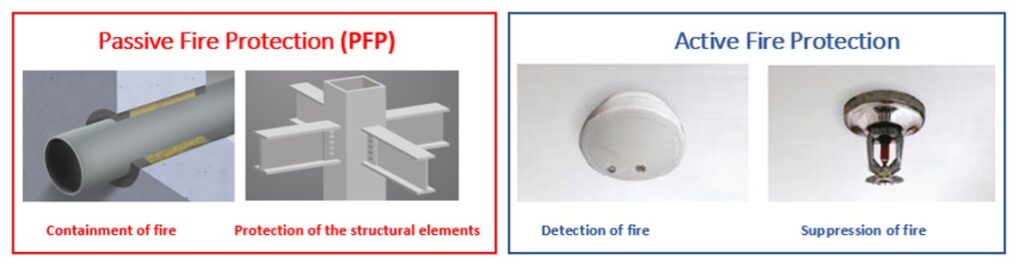
Source: nullifire.com
Active Fire Protection Systems:
- Automatic sprinkler systems
- Smoke and fire detector and alarm systems
- Water supply systems, hose cabinets, fire extinguishers
- Fire department response systems
Passive Fire Protection Systems:
- Construction materials with limited combustion characteristics
- Compartmentalized design with fire barriers, fire doors, and dampers
- Structural fire protection materials like spray-applied fire resistive materials (SFRM), gypsum board enclosures, and intumescent coatings
Effectiveness of Sprinkler Systems
Automatic sprinkler systems are highly effective and reliable when properly designed, installed, and maintained. They significantly reduce the chances of dying in a fire and the average property loss. The National Fire Protection Association (NFPA) reports no record of a fire killing more than two people in fully sprinklered public buildings where the system functioned correctly.
Stages of Fire Development
Understanding the stages of fire development is crucial for effective fire protection:
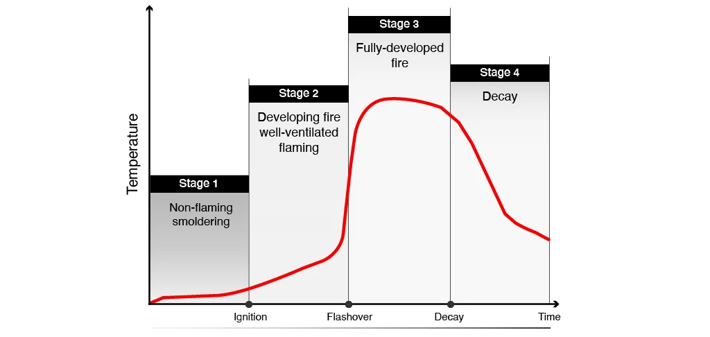
Source: firetrace.com
- Incipient Ignition Phase: Heating of potential fuel sources.
- Growth Stage: Ignition with visible flaming combustion.
- Burning Period (Flashover): Full-room involvement in fire, causing the most severe effects on building elements.
- Decay Period: Fire dies out as fuel becomes exhausted.
Preventing ignition or extinguishing the fire during the early growth stage is the most effective means of ensuring fire safety.
Fire Resistance Ratings and ASTM E119
Fire resistance is measured by how long a structural assembly can maintain its integrity, stability, and temperature transmission under standard fire conditions, typically using the ASTM E119 test method. This standard test exposes structural elements to a controlled fire with specific time-temperature curves to assess their fire endurance.
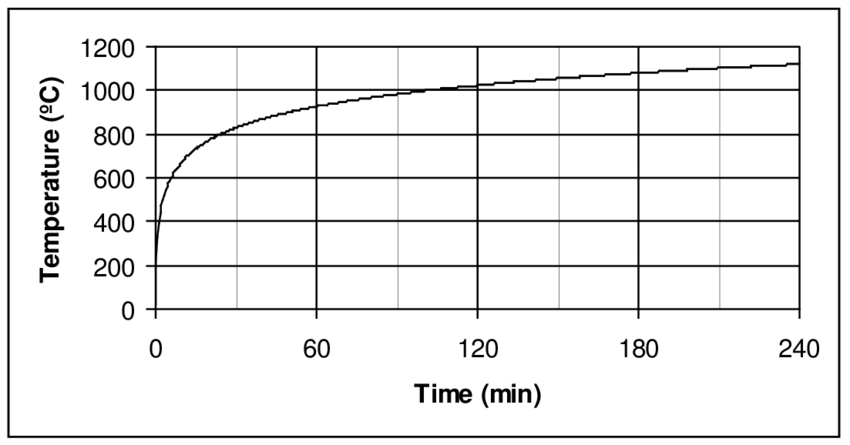
Source: Researchgate.net
Key points about the ASTM E119 standard:
- Represents the most intense stage of a fire.
- Does not include the decay phase, unlike natural fires.
- Provides a consistent baseline for comparing fire resistance across different materials.
Steel’s Performance in Fire
Steel is inherently fire resistant but loses strength and stiffness at elevated temperatures. At around 1,100 °F (593 °C), steel retains about 50% of its strength. At 1,300 °F (704 °C), it retains about 20%. Steel does not melt in building fires, which typically do not exceed temperatures of 2,000 °F (1,093 °C).
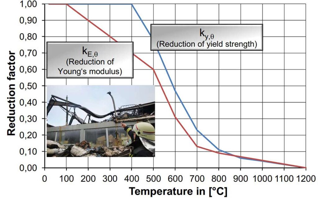
Source: heissbemessung.net
Fire Protection Materials for Steel
Various materials and methods are used to protect steel from fire:
Spray-Applied Fire Resistive Materials (SFRM):
- Mineral Fiber SFRM: Lightweight and non-combustible.
- Cementitious SFRM: Made from binders like gypsum and Portland cement with aggregates like vermiculite or perlite.

Source: carboline.com
Intumescent Coatings:
- Expand upon heating, forming an insulating layer.
- Suitable for aesthetic and exposed applications.
Other Methods:
- Concrete or masonry encasement.
- Filling tubular steel columns with concrete.
- Using rated suspended ceilings and enclosure systems.
The First Interstate Tower fire in Los Angeles in 1988 serves as a notable case study in fire safety for steel buildings. An unusually good application of fire resistive coating on the building’s steel structure played a crucial role in maintaining its structural integrity during the fire. This effective fireproofing measure helped prevent the collapse of the steel frame, demonstrating the importance of proper fire resistive coating in ensuring the resilience of steel buildings under extreme fire conditions.
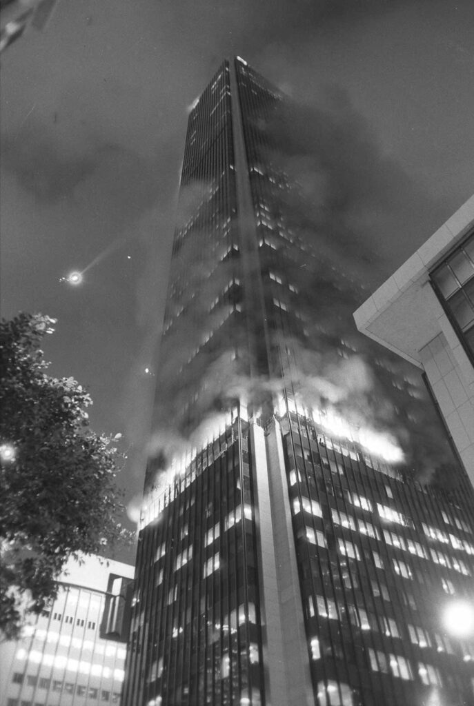
Source: Wikimedia / Thomas Kelsey
Worked Example According To Eurocode Standards
Structure Definition
- 2 storey office building
- Standard Fire Resistance Requirement R30
- 2 span continuous composite slab
Actions:
- Self weight of composite slab – 2.05 kN/m2
- Self weight of steel beams
- Permanent Load – 2.5 kN/m2
- Imposed Load – category C2 (p)- 4.00 kN/m2
- Snow – 1.20 kN/m2
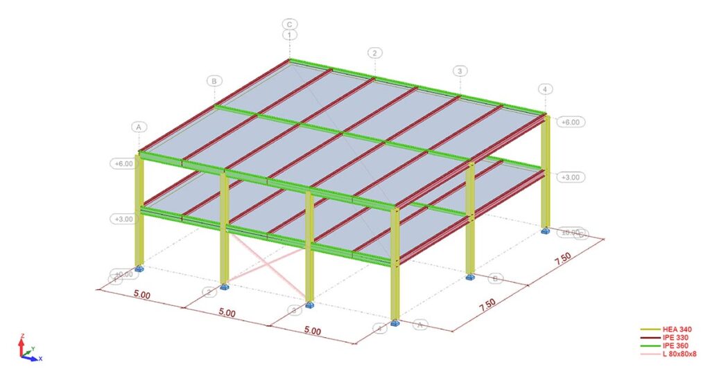
In this example, the critical temperature and actual temperature of the main beams IPE 360 will be calculated. If the required fire resistance cannot be provided by the structural element, fire protection calculations will be performed.
Main Beams are simply supported by columns and carry secondary beams of composite slab. IPE 360 profiles of steel grade S275.
Bending Moment: Mfi,Ed = 180 kNm
Shear forces: Vfi,Ed = 72.7 kN
According to EN 1990 fire load combination is as follows:
![\[ E_{fi,d,t} = \sum_{j \geq 1} G_{k,j} + \psi_{1,1} Q_p + \psi_{2} Q_{s} = \sum_{j \geq 1} G_{k,j} + 0.7 Q_p + 0 Q_s \]](https://steelexplained.com/wp-content/ql-cache/quicklatex.com-f846f1cee4b07c236a701183baeaa5eb_l3.png "Rendered by QuickLaTeX.com")
where:
- Gk,j – Permanent Actions (self weight)
- Qp – Leading Variable Action (imposed load)
- Qs – Other Variable Actions (snow load)
Fire combinations are different than the ones for the room temperature, load factors are lower as for room temperature, because according to EN 1990 fire load combination is accidental situation.
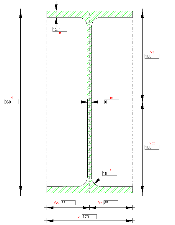
Cross Section Class
We first calculate the reduction factor for steel grade S275, so we can find the cross section class:
![\[ \varepsilon = 0.85 \sqrt{\frac{235}{275}} = 0.79\]](https://steelexplained.com/wp-content/ql-cache/quicklatex.com-d73c35be067d6f5c0302ac0ea093bc1c_l3.png "Rendered by QuickLaTeX.com")
Classification of the cross section:
- The class of the web in bending:
![\[\frac{c}{t_w} = \frac{29.9}{0.80} = 37.30 < 72\varepsilon = 56.88 \rightarrow \text{Class 1}\]](https://steelexplained.com/wp-content/ql-cache/quicklatex.com-716a994bb48cb5775e64ab9edf331201_l3.png "Rendered by QuickLaTeX.com")
- The class of the flange in compression:
![\[\frac{c}{t_f} = \frac{6.30}{1.27} = 4.96 < 9\varepsilon = 7.1 \rightarrow \text{Class 1}\]](https://steelexplained.com/wp-content/ql-cache/quicklatex.com-4044fb4913e5df7515fddcf55295345c_l3.png "Rendered by QuickLaTeX.com")
The cross section is class 1!
Class 1 cross sections can form a plastic hinge with the rotation capacity required without reducing the cross section resistance.
Critical Temperature
Now we need to calculate the critical temperature. For this we need first to find the degree of utilization. Critical temperature is the temperature to which structural element maintains its capacity. The collapse occurs when the design temperature of structural element equals its critical temperature.
- Plastic section modulus: Wpl = 1019 cm3
- Shear Area: Av = 35.14 cm2
- Yield strength of steel: fy = 275 N/mm2
Design moment resistance of a member at room temperature:
![\[M_{Rd} = \frac{W_{pl} f_y}{\gamma_M0} = \frac{1019*275}{1} * \frac{1}{1000} = 280.22 kNm\]](https://steelexplained.com/wp-content/ql-cache/quicklatex.com-b9cbc82a8d75ff615f0e47e8b2a45f0b_l3.png "Rendered by QuickLaTeX.com")
Design shear resistance of a member at room temperature:
![\[V_{Rd} = \frac{A_v f_y}{\sqrt{3}\gamma_M0} = \frac{35.14*275}{\sqrt{3}*1} * \frac{1}{10} = 557.92 kN\]](https://steelexplained.com/wp-content/ql-cache/quicklatex.com-3f991ed5b079ec1e5b5a4ef9748f18c7_l3.png "Rendered by QuickLaTeX.com")
Degree of utilization:
![\[\mu_{0,M} = \frac{M_{fi,Ed}}{M_{Rd}} = \frac{180}{220} = 0.642\geq0.013\]](https://steelexplained.com/wp-content/ql-cache/quicklatex.com-059920c993825130a3bd16e91ec3e347_l3.png "Rendered by QuickLaTeX.com")
![\[\mu_{0,V} = \frac{V_{fi,Ed}}{V_{Rd}} = \frac{72.7}{557.92} = 0.13\geq0.013\]](https://steelexplained.com/wp-content/ql-cache/quicklatex.com-b62f5e22850302638db9fd039dc88482_l3.png "Rendered by QuickLaTeX.com")
![\[\mu_{0} = max(\mu_{0,M}, \mu_{0,V}) = 0.642 \]](https://steelexplained.com/wp-content/ql-cache/quicklatex.com-8c5629dfcc59389b37fcf5d95f2b4f47_l3.png "Rendered by QuickLaTeX.com")
Critical Temperature:
![\[ \theta_{a,\text{cr}} = 39.19 \ln \left( \frac{1}{0.9674\mu_{0}^{3.833}} - 1 \right) + 482 \]](https://steelexplained.com/wp-content/ql-cache/quicklatex.com-b7f00f8cadbc8ee85e767c2b55b89ddc_l3.png "Rendered by QuickLaTeX.com")
![\[ \theta_{a,\text{cr}} = 39.19 \ln \left( \frac{1}{0.9674*0.642^{3.833}} - 1 \right) + 482 = 542.13^\circ \text{C} \]](https://steelexplained.com/wp-content/ql-cache/quicklatex.com-586b3527b6acc4bc9a649aae4768fcf1_l3.png "Rendered by QuickLaTeX.com")
Temperature of Unprotected Steel Section
Now we need to calculate the actual temperature of the unprotected steel sections after 30 minutes of standard fire exposure on all four sides.
At the starting moment t = 0s, and the temperature is 20oC
![\[ t = 0 s \]](https://steelexplained.com/wp-content/ql-cache/quicklatex.com-b85cc6e076dcbfb9e7f10f6147e88061_l3.png "Rendered by QuickLaTeX.com")
![\[ \theta_{m} = 20^\circ \text{C} \]](https://steelexplained.com/wp-content/ql-cache/quicklatex.com-780353751d235bc2e9ddcd1466f749b3_l3.png "Rendered by QuickLaTeX.com")
Section factor, box value of the section factor and the correction factor for the shadow effect:
Lets learn first what is section factor?
The section factor describes the rate of heating of cross section. It is the ratio of the perimeter of the steel section exposed to fire and the cross section area of the steel element. The higher the section factor, the faster the temperature of the steel member increases during a fire.
![\[\frac{A_{m}}{V} = 186.25 \; m^{-1}\]](https://steelexplained.com/wp-content/ql-cache/quicklatex.com-1e23420da4a601abf8d0fc7360444531_l3.png "Rendered by QuickLaTeX.com")
where:
- Am – Steel perimeter exposed to fire
- V – Cross section area
Box value of the shadow factor:
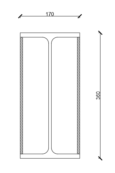
![\[[\frac{A_{m}}{V}]_{b} = \frac{106}{72.7} = 145.8 \; m^{-1}\]](https://steelexplained.com/wp-content/ql-cache/quicklatex.com-c4006fec8bc9cbfa4604618907bc0da9_l3.png "Rendered by QuickLaTeX.com")
Correction factor for the shadow effect, shadow effect is active at the concave member surfaces:
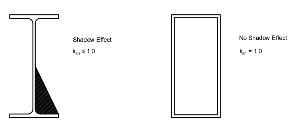
![\[ k_{sh} = 0.9 * \frac{145.8}{186.25} = 0.70 \]](https://steelexplained.com/wp-content/ql-cache/quicklatex.com-e98b7496b4b242ccd30b0ae3c4644d22_l3.png "Rendered by QuickLaTeX.com")
Learn more about the shadow effect in EN 1991-1-2 : Annex G
First time interval t1 can be taken as follows:
![\[\Delta t = 5s \implies t_1 = 0 + \Delta t = 5s \]](https://steelexplained.com/wp-content/ql-cache/quicklatex.com-795b9bd465c191c4de0e460361416318_l3.png "Rendered by QuickLaTeX.com")
Gas temperature of the fire compartment is calculated using the standard temperature-time curve:
![\[\theta_{g} = 20 + 345 \log_{10} (8* t_1 / 60 + 1) = 96.54^\circ \text{C}\]](https://steelexplained.com/wp-content/ql-cache/quicklatex.com-8673d5f374168ebce7a4885de689ca0c_l3.png "Rendered by QuickLaTeX.com")
Specific heat of steel is temperature dependent and is calculated to EN 1993-1-2 3.4.1.2:
![\[c_a = 425 + 0.773 * \theta_{m} - 0.00169 * \theta_{m}^2 + 0.00000222 * \theta_{m}^3\]](https://steelexplained.com/wp-content/ql-cache/quicklatex.com-34626365d0563138d4441be93f480216_l3.png "Rendered by QuickLaTeX.com")
![\[c_a = 439.8 \, \text{J/kgK}\]](https://steelexplained.com/wp-content/ql-cache/quicklatex.com-74273969e3bad67343555a3f364ce0e8_l3.png "Rendered by QuickLaTeX.com")
- θm – Temperature of the surface of steel element
Net heat flux can be calculated to EN 1991-1-2 3.1:
![\[h_{net} = \alpha_c (\theta_{g} - \theta_{m}) + \Phi \epsilon_m \epsilon_f \sigma \left[ (\theta_{r} + 273)^4 - (\theta_{m} + 273)^4 \right]\]](https://steelexplained.com/wp-content/ql-cache/quicklatex.com-118ef53ed57a6e7c6df67473d3dda93c_l3.png "Rendered by QuickLaTeX.com")
![\[h_{net} = 2361.07 \, \text{W/m}^2\]](https://steelexplained.com/wp-content/ql-cache/quicklatex.com-937c521b71efe49bf639565a49406f8c_l3.png "Rendered by QuickLaTeX.com")
where:
- α = 25 W/m2 K – convection heat transfer coefficient EN 1991-1-2 3.2.1
- εm = 0.7 – emissivity of the steel surface EN 1991-1-2 3.1(6)
- εf = 1.0 – emissivity of the fire flame EN 1991-1-2 3.1(6)
- σ = 5.67 * 10-8 W/m2 K4 – Stephan-Boltzmann constant EN 1991-1-2 3.1(6)
- Φ = 1.0 – view factor EN 1991-1-2 3.1(7)
- θr – radiation temperature of the fire – θr = θg for fully fire engulfed members
The increase in steel temperature of the member in the interval Δt can be calculated as follows:
![\[\Delta \theta_{a,t} = k_{sh} * \frac{ A_m / V} {c_a \rho_a} h_{net} \Delta t\]](https://steelexplained.com/wp-content/ql-cache/quicklatex.com-4160c24eb291286dd3fe2b60b36560da_l3.png "Rendered by QuickLaTeX.com")
![\[\Delta \theta_{a,t} = 0.7 * \frac{186.25} {439.8 * 7850} * 2361.1 * 5 = 0.449^\circ \text{C}\]](https://steelexplained.com/wp-content/ql-cache/quicklatex.com-505ba99a9269cf0327a26175c2191471_l3.png "Rendered by QuickLaTeX.com")
And finally we can calculate the temperature in the steel section in the first iteration:
![\[\theta_{m} = \theta_{m} + \Delta \theta_{a,t}} \implies 20 + 0.449 = 20.449^\circ \text{C}\]](https://steelexplained.com/wp-content/ql-cache/quicklatex.com-c1c02fac9fc62f7eed0fb98890843f5d_l3.png "Rendered by QuickLaTeX.com")
Now we continue with the second iteration and so on:
![\[t_2 = t_1 + \Delta t = 5 + 5 = 10 \text{s}\]](https://steelexplained.com/wp-content/ql-cache/quicklatex.com-5512eb3af45f5eda1c67cec00ed5761b_l3.png "Rendered by QuickLaTeX.com")
![\[\theta_{g} = 146.95^\circ \text{C}\]](https://steelexplained.com/wp-content/ql-cache/quicklatex.com-391ba27d30f078e7a4b14c83cabeb5d7_l3.png "Rendered by QuickLaTeX.com")
![\[\quad c_a = 440.12 \, \text{J/kg K}\]](https://steelexplained.com/wp-content/ql-cache/quicklatex.com-6016b3df00f2a3975f5703ebc0591278_l3.png "Rendered by QuickLaTeX.com")
![\[h_{net} = 4102.74 \, \text{W/m}^2 \]](https://steelexplained.com/wp-content/ql-cache/quicklatex.com-4389e5d4359e18e051be6a7f6d03c46d_l3.png "Rendered by QuickLaTeX.com")
![\[\Delta \theta_{a,t} = 0.779^\circ \text{C}\]](https://steelexplained.com/wp-content/ql-cache/quicklatex.com-5176c0896d2f3f65907962ece1c99d1b_l3.png "Rendered by QuickLaTeX.com")
![\[\theta_{m} = 20.449 + 0.779 = 21.23^\circ \text{C}\]](https://steelexplained.com/wp-content/ql-cache/quicklatex.com-06f89fcad00e32557980818db5064870_l3.png "Rendered by QuickLaTeX.com")
The next iterations are presented in this table:
| t [min] | 5 | 10 | 15 | 20 | 25 | 30 |
|---|---|---|---|---|---|---|
| θg [°C] | 576.41 | 678.43 | 738.56 | 781.30 | 814.60 | 841.80 |
| θa [°C] | 219.77 | 462.10 | 624.50 | 713.20 | 744.75 | 803.75 |
We can see that after 30 minutes of fire exposure, the steel temperature is 803.75 Co, critical temperature is reached after 12.17 minutes, so required fire resistance of R30 is not achieved. It means fire protection is needed.
Temperature of Protected Steel Section
Now we will calculate the temperature of the protected profile after 30 minutes of standard fire exposure on all sides.
The steel section is protected with fibre-silicate boards with the following parameters:
- ρp = 600 kg/m3 – unit mass
- cp = 1200 J/kgK – specific heat
- λp = 0.15 W/mK – thermal conductivity of fire protection
- dp = 0.02m – thickness of the fire protection
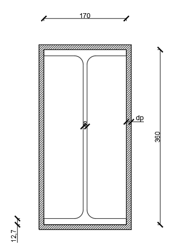
The section factor:
![\[\frac{A_{p}}{V} = 145.8 \; m^{-1}\]](https://steelexplained.com/wp-content/ql-cache/quicklatex.com-f5f08acbb7988e5302d44bbea83632fa_l3.png "Rendered by QuickLaTeX.com")
The unit mass of steel: ρa = 7850 kg/m3
For the protected steel member we will use time iterations of 30s, which is the maximum duration of time interval which we can use for protected steel sections according to Eurocode.
![\[\Delta t = 30s \implies t_1 = 0 + \Delta t = 30s \]](https://steelexplained.com/wp-content/ql-cache/quicklatex.com-9ceebbe35fde373993e506a8294aff3d_l3.png "Rendered by QuickLaTeX.com")
Gas temperature calculated using the standard temperature-time curve:
![\[\theta_{g,t} = 20 + 345 \cdot \log_{10}(8 * t_1 / 60 + 1) = 261.14^\circ\text{C}\]](https://steelexplained.com/wp-content/ql-cache/quicklatex.com-8a951846e965600ba45360f6547a41d6_l3.png "Rendered by QuickLaTeX.com")
![\[\Delta \theta_{g,t} = 261.14 - 20 = 241.14^\circ\text{C}\]](https://steelexplained.com/wp-content/ql-cache/quicklatex.com-715894462a752bf12a41d903a8e03bc3_l3.png "Rendered by QuickLaTeX.com")
Specific heat of steel is temperature dependent and is calculated to EN 1993-1-2 3.4.1.2:
![\[\theta_{a,t} = 20^\circ \text{C}\]](https://steelexplained.com/wp-content/ql-cache/quicklatex.com-c907d4db7cf7ff4e0bd8334d08eb91eb_l3.png "Rendered by QuickLaTeX.com")
![\[ c_a = 425 + 0.773 * \theta_{a,t} - 0.00169 * \theta_{a,t}^2 + 0.00000222 * \theta_{a,t}^3\]](https://steelexplained.com/wp-content/ql-cache/quicklatex.com-b491f80c8fb073548bc529700fc5522a_l3.png "Rendered by QuickLaTeX.com")
![\[ c_a = 439.8 \, \text{J/kg K}\]](https://steelexplained.com/wp-content/ql-cache/quicklatex.com-95ae99e3530133622873a282a77cf4cf_l3.png "Rendered by QuickLaTeX.com")
The amount of heat stored in the protection:
![\[\phi = \frac{c_p \rho_p d_p A_p}{c_a \rho_a V} = \frac{1200 * 600 * 0.02}{439.8 * 7850} * 145.8 = 0.61\]](https://steelexplained.com/wp-content/ql-cache/quicklatex.com-8123b5a212ddeb1f2aa6dda1e6669d6c_l3.png "Rendered by QuickLaTeX.com")
The increase in steel temperature of the member in the interval Δt can be calculated as follows:
![\[\Delta \theta_{a,t} = \frac{\lambda_p A_p I / V (\theta_{g,t} - \theta_{a,t})}{d_p c_a \rho_a (1 + \phi / 3)} \Delta t - (e^{\phi / 10} - 1) \Delta \theta_{g,t}\]](https://steelexplained.com/wp-content/ql-cache/quicklatex.com-cf5c42bdc83d363de7405fe7f4928def_l3.png "Rendered by QuickLaTeX.com")
![\[\Delta \theta_{a,t} = \frac{0.15 * 145.8 * 241.14 * 30}{0.02 * 439.8 * 7850 * (1 + 0.61 / 3)} - \left( e^{0.61 / 10} - 1 \right) * 241.14 = -13.2^\circ \text{C}\]](https://steelexplained.com/wp-content/ql-cache/quicklatex.com-f2bc1c676266f2001fb3c24abc31260b_l3.png "Rendered by QuickLaTeX.com")
Negative increments of the steel temperature are not allowed:
![\[\Delta \theta_{g,t} = 241.14^\circ \text{C} \geq 0 \implies \Delta \theta_{a,t} = 0^\circ \text{C}\]](https://steelexplained.com/wp-content/ql-cache/quicklatex.com-7f6e470c334b25f1d4de866a2e174760_l3.png "Rendered by QuickLaTeX.com")
Second time interval t2 can be taken as follows:
![\[\Delta t = 30s \implies t_2 = 30 + \Delta t = 60s\]](https://steelexplained.com/wp-content/ql-cache/quicklatex.com-50d35927b4e5e2f98858a4e521e3c21a_l3.png "Rendered by QuickLaTeX.com")
After all the iterations, the results are presented in the table below:
| t [min] | 5 | 10 | 15 | 20 | 25 | 30 |
|---|---|---|---|---|---|---|
| θg [°C] | 576.41 | 678.42 | 738.56 | 781.35 | 814.60 | 841.80 |
| θa [°C] | 36.33 | 74.64 | 116.40 | 158.33 | 199.30 | 238.85 |
The temperature of the steel section after 30 min of fire exposure is 238.85 °C.
![\[\theta_a = 238.85^\circ \text{C} < \theta_{d,cr} = 542.13^\circ \text{C}\]](https://steelexplained.com/wp-content/ql-cache/quicklatex.com-957eee0bd9f8ec5e79099a06033cc40f_l3.png "Rendered by QuickLaTeX.com")
Main beams fulfill standard fire resistance requirement R30!
Conclusion
The first critical temperature was determined to be 542.13°C. Subsequently, we calculated the temperature progression in an unprotected steel section. It became evident that the critical temperature was reached after 12.17 minutes of standard fire exposure. Therefore, we concluded that the steel section must be insulated to meet the required fire protection standard of R30. We chose fire protection using fibre-silicate boards. After evaluating the temperature development in the protected steel section, it was demonstrated that after 30 minutes, the steel section’s temperature remained below the critical threshold. So, the fire-protected steel element meets the R30 standard fire resistance requirement.
Fire safety in steel buildings involves a comprehensive approach combining active and passive fire protection systems. Understanding the stages of fire, the performance of steel under fire conditions, and the role of fire protection materials is essential for designing and maintaining fire-resistant structures. Adhering to standards and ensuring proper application and inspection of fire protection systems will enhance the safety and resilience of steel buildings against fire hazards.
By prioritizing fire safety in the design and construction of steel buildings, we can better protect lives and property, ensuring that these structures stand strong even in the face of fire.
References:
- American Institute of Steel Construction, Inc. (2003). Facts for Steel Buildings—Fire.
- National Fire Protection Association (NFPA). Building Code (2003).
- European Committee for Standardization. (2002). Eurocode 1: Actions on Structures – Part 1-2: General Actions – Actions on structures exposed to fire (EN 1991-1-2).
- ECCS (2001). Yield Strength Retention Factors for Structural Steel at Elevated Temperatures.
- Gann, R.G., et al. (1994). Study on Smoke Inhalation Casualties.
- GRsoft. (n.d.). – www.grsoft.eu/
- Rohr, K. (2001). NFPA Report on Sprinkler System Performance.
- ASTM E119 Standard Test Method for Fire Tests of Building Construction and Materials.


